5


DSOS
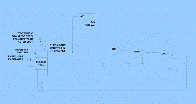
Simplified Block Diagram
Simplified Block Diagram


| This is a
simplified block diagram of a single channel. |
|
| Starting on the
left is the standoff assembly which consists of a mounting bracket, embedded
thermistor, Peltier device, and heat exchanger. |
|
| The thermisor is
wired to an A/D input. The
desired setting is output by the D/A.
The difference of the thermistor and desired setting is used to
determine the drive level to the Peltier device. |
|
| ~Melanie Leong~ |