This design showed so much promise that it caught the imagination of the director of OVRO, Al Moffet, a Caltech professor of radio astronomy and an expert in interferometry techniques. Together with Neugebauer and Leighton, he proposed to the NSF to build three antennas as a millimeter-wave interferometer in the Owens Valley, together with a fourth, more accurate version, to be sited on a high mountain. The basic idea behind this back-up structure was that an array of posts parallel to each other and to the optic axis would support the reflecting surface in the correct shape if they were held together in a rigid structure with struts [1][2]. The struts had to be attached to the posts in such a way that the axes of the struts, connected to an end of a post, had to all pass through the same point along the axis of the post. In this way there would be no net twisting or bending force on a post. Struts from the ends of each post to adjacent posts made up the rigid array. In order to keep all forces calculable by the BASIC program used, Leighton insisted that all joints be pinned rather than welded, since welding could introduce unknown shear forces. This resulted in a stiff and homologous structure.
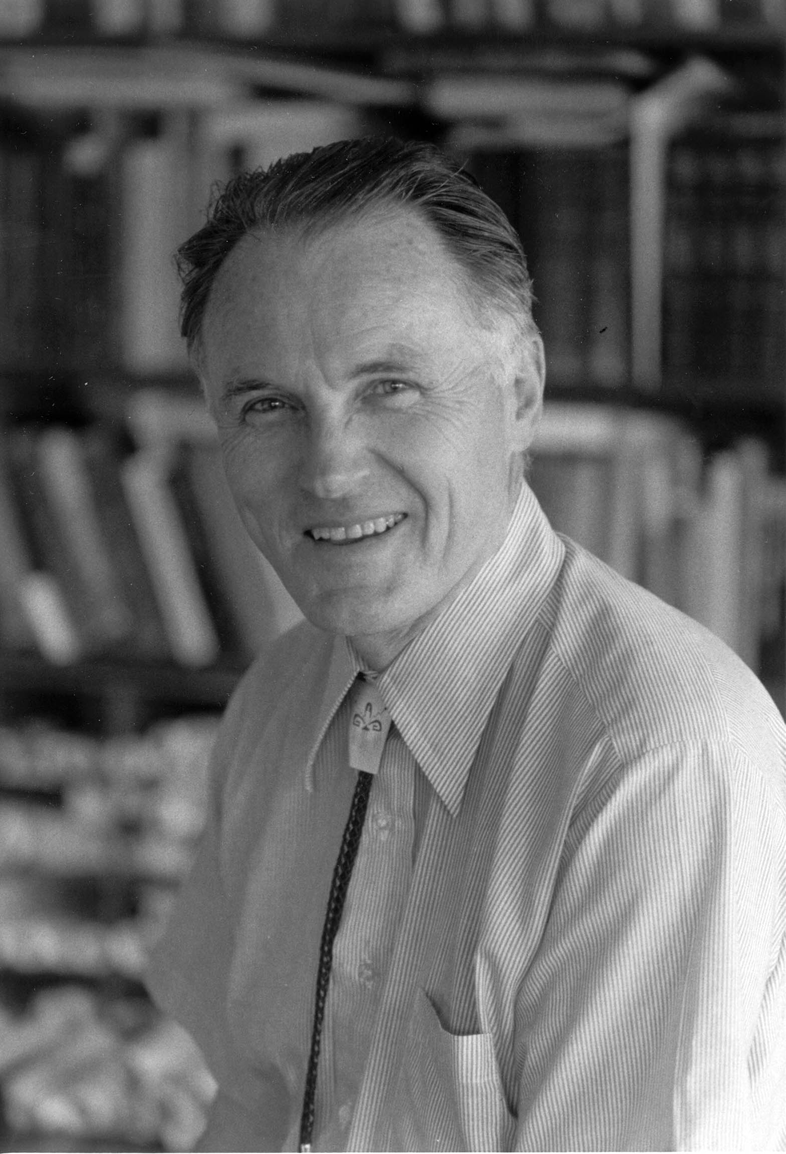
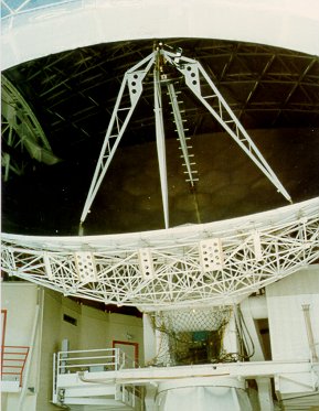
Figure 2. Leighton standing on the back-up structure. Once the struts and posts were constructed in the shop the support structure was very easy to build. The next problem was how to make the reflecting surface. That was solved by using aluminum honeycomb to produce each of 84 hexagonal panels (the edge panels have a more complex shape) which were fitted together to form the 10.4 meter dish. Each panel was supported from the back-up structure by three adjustable stand-off pins. Each pin was shared by two other adjacent panels. Differential jack screws connected the ends of the pins to the panels. This enabled very fine mechanical control of the surface position.
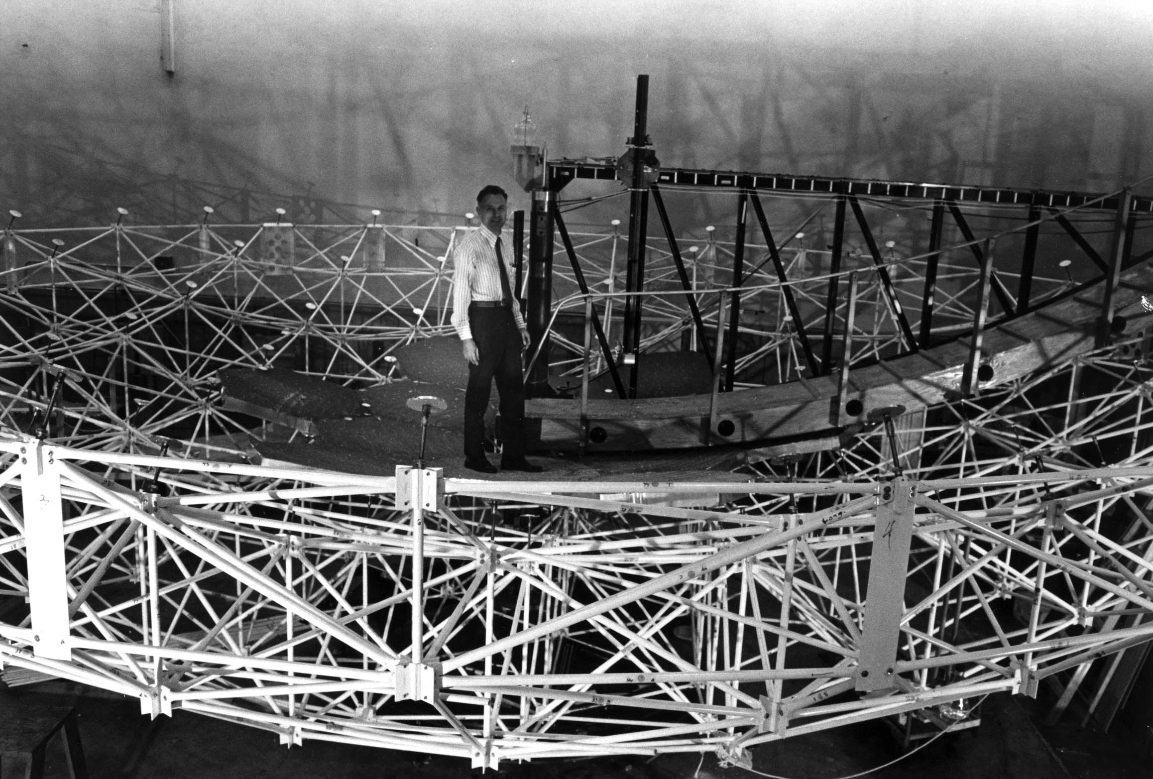
Figure 3. Details of the back-up structure. Near the center is a support pin and its associated jack-screw. The upper surfaces of the honeycomb panels were then shaped by rotating the entire dish on a carefully constructed air bearing, under a cutting tool. This tool ran up and down a precision parabolic track, set by laser interferometry relative to a horizontal level consisting of an oil tray, thus producing the desired parabolic shape. Sheet aluminum of specially made uniform thickness was epoxied to the aluminum honeycomb surface. The back of each honeycomb panel was covered with a layer of styrofoam for insulation. Finally, the aluminum surface was ground to remove fine-scale variations due to thickness or honeycomb variations. After several iterations of grinding and measurement, the dish achieved a test rms of 10 µm, on the air bearing, in the zenith. A mirror-like polish to the dish may have been desirable, but the dangers of the Sun being imaged on some vulnerable surface precluded this. To minimize this hazard, the surface was polished only to a satin-like finish. Even so, it has happened that during a testing or construction operation, the Sun was inadvertently focused on a secondary mirror feed leg and melted some electrical cables running along the leg! Thus, great care was, and still is, needed when exposing the dish to the Sun. To this day, this is one of the reasons observations are not routinely made during the daytime, although theoretically possible. Another, and perhaps more immediate, reason is that exposing the dish to the Sun will heat it differentially and cause deterioration of the surface figure. In the case of the 1991 total solar eclipse, Dr. Hal Zirin of Caltech, for his observations, provided a tent-like cover for the dish, transparent to submillilmeter radiation but protecting the dish from heating. (See Fig. 44 in the Photo Gallery section)
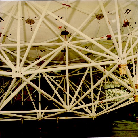
Figure 4. The feed legs which support the secondary mirror. Thermal stability is a critical aspect of a metal telescope, and for that reason Leighton used the thermally controlled large building, that had previously housed the Palomar 200 inch mirror, for the CSO dish construction. The dish is constructed so that the surface panels are demountable and the back-up structure is disassembleable into a few easily transportable pieces. Thus, a notable feature is that the dish may be disassembled and reassembled with only a moderate loss of accuracy. The means for adjustment were provided, as mentioned above, by the differential screws at the bottom of each stand-off pin, and also by a warping harness for each panel, and, potentially, by heater coils that had been built into the hexagonal panels. (It is not clear how these heaters were intended to function, and they were never used. Instead, the idea of heating or cooling the stand-off pins connecting the panels to the screw jacks was proposed.) These features were needed because of the plan to build all telescope components and the dome in Pasadena for later disassembly and shipment to Mauna Kea, for reassembly on the mountain. The plan permitted testing, adjustment, and possible modifications to be made near where the industrial and technical services are located. This plan included not only the dish but the entire dome. However, the dish itself was never installed on the alt-azimuth mount until all other construction was completed on Mauna Kea. After installation of the dish on Mauna Kea, the surface accuracy had degraded to 40 µm. The errors were partially removed by spinning the dish in the vertical under a replica of the Pasadena parabolic track and mechancally measuring deviations from the track. First order corrections were made by means of the differential screws. Second order surface measurements were made by means of a novel "holography" device designed and built by Serabyn, Phillips, and Masson [3]. This method also allowed measurements to be made at various elevation angles. Errors detected by these methods were also corrected by manually adjusting the differential screws. The telescope was "tuned" to optimize the performace at elevation angles of about 50 degrees. A surface accuracy of about 20 µm was obtained. The concept of heating or cooling the stand-off pins
using Peltier units,
to make fine, third order adjustments
and corrections for sag due to gravity, has been recently successfully implemented by CSO engineer
Melanie Leong [4]. The improvement in the efficiency has been about 50% at the highest frequencies.
REFERENCES
[1] Robert B. Leighton "A 10 Meter Telescope for Milllimeter and
    Submillimeter Astronomy" Technical Report for NSF Grant
    73-04908, 1978.
[2] David Woody, David Vail, and Walter Schaal "Design, Construction,
    and Performance of the Leighton 10.4-m-Diameter Radio Telescopes"
    Proceedings of the IEEE, Vol. 82, N0.5, May 1994.
[3] E. Serabyn, T.G. Phillips, C.R. Masson "Radio Telescope Surface
    Measurement with a Shearing Interferometer" in URSI Proceedings,
    Holography Testing of Large Radio Telescopes, 1991, 40.
[4] M. Leong, R. Peng, M. Martin,H. Hirosige,R. Chamberlin, T.G. Phillips
    "A CSO submillimeter adaptive optics system" in Prodeedings
    of the SPIE, Volume 6275, 2006, 21L.
|