Preparing for Observing
- Mailing List
- Manpower and
Instrument Support
- Arrival and Vehicle
Logistics
- Weather Multiplexing
- alpha1, UIP, and Where to Put
Your Macros
- Entering Your Sources
in the UIP Catalog
- Bolocam Macro
Structure
- Changing Scan
Direction or Coordinate System
- Scan Angle and Dewar
Rotation and Obtaining Full Sampling
- How Array Orientation
Affects Sampling
- Important Coordinate
Systems and Angles
- Converting Scan Angle
to Rotator Angle
- The Optimal Scan Offset Angle
and the Available Rotation Range
- Enabling Dewar
Rotation
- Designing Your Scan
Pattern and Calculating Expected
Coverage (esp. for Small Maps)
- Cross-Linking
- Calibration
Observations
- Pointing and Flux
Calibrator Catalogs
- Suggested Calibration
Schedule and Macros
- Calibrating the Dewar
Rotator
- Revision History
Back to BolocamWebPage
Back to ExpertManual
Mailing List
If you would like to be notified by email when important updates of
interest to Bolocam observers are ready, please contact the Bolocam support person,
to be added to our Bolocam users mailing list.
Manpower and
Instrument Support
At the CSO, there must be two people at the summit at any given time
for safety reasons. If you are scheduled for the entire night,
you are responsible for providing those two observers. If you are
scheduled for a half-night, typically each half-night observer is
responsible for only one observer and both half-night observers will
stay at the summit the entire night to cover each other. If you
would like to coordinate with the other half-night observer for your
night, please contact Rena
Becerra-Rasti to get contact information.
Depending on the situation, there may be a Bolocam instrument team
member at the summit or on call at Hale Pohaku (HP) (the dorm at 10000
feet) or in Hilo. The names and contact information
for these instrument team members will be posted in both the HP office
and at the summit.
In the case that we have made arrangements to observe during your
unused morning hours, we will have 2 instrument team members to cover
that observing. These people will not be available all night
(because they will be observing into the morning), but they will take
emergency calls and can help you get started in the early evening if
necessary.
Cryogen fills and cycling of the refrigerator will in general be
covered by the day crew.
We would like to move as quickly to a situation where the available
documentation is sufficient for observing and no instrument team
members are needed. We therefore encourage you strongly to rely
on this documentation whenever possible and to call an instrument team
member only as a last resort, and to please let us know if you find the
documentation lacking so that we can improve it! Please make
notes in either the paper copy of the documentation on the summit or
send email to the Bolocam support person.
Arrival and Vehicle
Logistics
In general, observers will need to rent their own car to travel from
either Kona or Hilo to Hale Pohaku (HP) and then will be provided a CSO
4WD vehicle for trips between HP and the summit. There is a
special discount number with Avis for such rentals. You are also
responsible for ensuring that HP reservations are made for you.
Information is available on the main CSO web page, http://www.cso.caltech.edu,
under Logistics. In general, the contact person for these
logistical issues is Diana Bisel,
the administrative aide at CSO Hilo office. Even if you make all
your own arrangements, please inform Diana of your flight, car rental,
and HP arrangements.
Weather Multiplexing
The official weather multiplexing policy is available at http://www.submm.caltech.edu/cso/observers/.
Be sure to read it so you understand how weather-multiplexed
observations work; you may be required to release the telescope under
certain conditions.
alpha1, UIP, and Where to Put
Your Macros
As those of you have used the CSO before know, the observer commands
the telescope via the User Interface Program (UIP), which runs on the
VAX/VMS machine alpha1.submm.caltech.edu.
We refer observers to the official CSO Manual, available on the main
CSO web page (http://www.cso.caltech.edu),
for a complete description of UIP and
the available commands. We will use a few of these commands
below. Realize that VMS and UIP are not case-sensitive.
You are not allowed to log in directly to alpha1 from most IP addresses,
but you can first ssh to kilauea.submm.caltech.edu and
then telnet from there to
alpha1. If you do
not have an account on alpha1,
you should just use the bolocam
account, ask a Bolocam team member for the password. If you do
have an account, you are welcome to use that account or the bolocam account, whichever you
prefer. If you use the bolocam
account you will have easy access to the already-written macros as well
as the bolocam
UIP source catalog (see below), but you will also be sharing with other
users and so may find the account less organized than you would
like.
Your ability to operate Bolocam does not depend on which UIP account
you use. (If you have an account on alpha1 but not on kilauea, ask Ruisheng Peng to set up an
account for you on kilauea.
If you do not have an account on alpha1,
you can also just use the bolocam
account on kilauea to get
to alpha1; again, ask a
Bolocam team member for the password).
Regardless of which account you use, the first thing you must always do upon entering UIP (when
observing -- unnecessary if just entering UIP to add sources or check
the help on a command) is type the command
UIP>
INSTRUMENT BOLOCAM
This informs UIP and the antenna computer to go into "Bolocam mode",
which includes some specific details about pointing, commanding the
instrument rotator, etc. To tell the telescope to observe a
particular source (see below for details
on making UIP aware of specific source), type
UIP>
OBSERVE SOURCE_NAME
or, if the source is a planet (or a comet or other object with quickly
varying equatorial coordinates)
UIP>
PLANET PLANET_NAME
Then, to execute a macro for observing the source, simply type
UIP>
EXECUTE MACROFILE.MAC
where MACROFILE.MAC is
the name of your observing macro (see below
and the remainder of this page for details on how to write
macros). By default, UIP assumes that all macros to be used are
in the home directory of the account you have logged into alpha1 with (e.g. in USER:[BOLOCAM] if you have
logged in as bolocam).
Of course, most of us never learned or can't remember how to navigate
in VMS. Fortunately, the alpha1
home
directories are cross-mounted to kilauea
in the /user_vax
directory; for example, USER_DIR:[BOLOCAM]
is cross-mounted on kilauea
as /user_vax/bolocam.
Most observers will find it much easier to edit their
macros in the familiar Unix environment on kilauea (using emacs or vi) than in the VMS
environment on alpha1.
Then all you have to do on alpha1
is EXECUTE the macro
inside UIP. emacs is available on alpha1, so you can edit on alpha1 in a pinch.
Entering Your Sources
in the UIP Catalog
Here we provide some pointers on entering sources in the UIP
catalogs.
To observe a particular source at the CSO, the UIP must be aware of the
source name and coordinates. Inside UIP, there are by default two
catalogs available: the Default catalog and the private catalog
associated with the login account you are using on the UIP computer (alpha1.submm.caltech.edu).
You can have additional catalogs, or load a different user's
catalog.
Look up "Source Catalogs" in the CSO Manual for more details.
Regardless, your source must be in an open catalog in order to observe
it.
You can set up your sources well ahead of time by logging in remotely
to the computer that runs the UIP, alpha1.submm.caltech.edu as
indicated above.
Once you have
logged in to alpha1, type
UIP at the VMS prompt and
accept the defaults for all the questions. You may receive a
message that another terminal is running UIP and your privileges will
be restricted; that's fine, you will still be able to inspect and
modify catalogs.
You can inspect which sources are in the currently available catalogs
by entering at the UIP prompt
UIP>
VERIFY *
This will give a listing of all sources in the currently open catalogs,
first grouped by catalog and then sorted by RA. Note that UIP
stores sources in B1950 coordinates, so the listing will be in B1950
coordinates. To get a listing in J2000 coordinates, type
UIP>
VERIFY * /NEW
To add a source to the current private catalog (you can't modify the
default catalog), type
UIP>
SOURCE SOURCE_NAME
You will receive a set of prompts requesting the source coordinates,
velocity, epoch, etc. The epoch may be "1950" (for B1950) or
"2000" (for J2000). You can enter sources in other coordinate
systems (e.g., galactic); type
UIP>
HELP SOURCE
to see the full set of options. To remove a source, type
UIP>
FORGET SOURCE_NAME
Note that UIP will happily let you create two sources with the same
name (and different coordinates), and it's not clear how it chooses
which one to use, so be sure to make sure there are no sources with
your desired source name first! If you end up with multiple
versions of the same source name, you can issue FORGET commands to get rid of
them; each FORGET command
removes one copy. There is some method to distinguish these
multiple copies using qualifiers (see the UIP online help), but you are
strongly encouraged to keep life simple by not making multiple copies
of the same source name.
When naming sources, some characters are not allowed or make life
inconvenient later. We suggest the following substitutions:
original
substitute
+ P
-
M
space
_
/
_
\ _
If the source has an alternate but frequently used name, try to include
it in the catalog
name so it will be obvious; e.g., the bolocam catalog contains the
source 0316P413_3C84,
which is also known as 0316+413
or 3C84.
If you want to check your source's catalog coordinates, type
UIP>
VERIFY SOURCE_NAME
again, include the /NEW
modifier if you want to see the J2000 coordinates. The VERIFY command accepts more
complex wildcards; for example, to see all sources beginning with 3C, just type
UIP>
VERIFY 3C*
If you want to find out the current local coordinates of a source, type
UIP>
VERIFY SOURCE_NAME /ALTAZ
WARNING: do not assume that, just
because a source is in the catalog,
it is entered with the right coordinates! Verify all your source
coordinates, we make no claims that the catalog is 100% accurate except
in the case of planets.
To observe a particular source, type
UIP>
OBSERVE SOURCE_NAME
Note that you do not need to enter planets in the catalog -- they are
already known to UIP -- and that, to observe a planet, you must use the
command
UIP>
PLANET PLANET_NAME
If you try to use OBSERVE
PLANET_NAME, you will find that the planet is not in the
catalogs.
Remember to add your sources to the Analysis Software source list,
cleaning params, mapping params, etc. files -- see the AnalysisSoftware
page for
details. They should be added with the same name as you have used
in the source catalog, though they should be left uncapitalized in the
these files. This goes for planets as well as normal sources.
Bolocam Macro
Structure
The simplest Bolocam macro one can write is the following:
c bolocam_example.mac

c

c sample macro for doing a raster scan with bolocam

ccccccccccccc


c first, toggle the observation number logic signal -- this tells our
software

c when an "observation" begins

c YOU MUST HAVE THESE THREE LINES AT THE START OF EVERY MACRO!

FLSIGNAL 128 /RESET

STARE 1

FLSIGNAL 128 /SET


c now, execute a raster scan

c parameters:

c    120 arcsec/sec scan speed

c    2280 arcsec scan length ( = 38 arcmin)

c    15 scans of this kind

c    162 arcsec separation between scans

c    scan in equatorial coordinates

c    alternate scans are done in opposite directions (to
minimize time between scans)

XRASTER_SCAN 120 2280 15 /STEP_SIZE = 162 /EQUATORIAL
/ALTERNATE_DIRECTION
/SETTLING_TIME = 3
c and set observation number low so we know we are done with command

c YOU SHOULD HAVE THIS LINE AT THE END OF EVERY MACRO

FLSIGNAL 128 /RESET
The above macro consists only of a setting of a logic signal (to
indicate to our analysis software that an observation is starting)
followed by execution of the XRASTER_SCAN
command. The logic signal is then reset at the end of the macro.
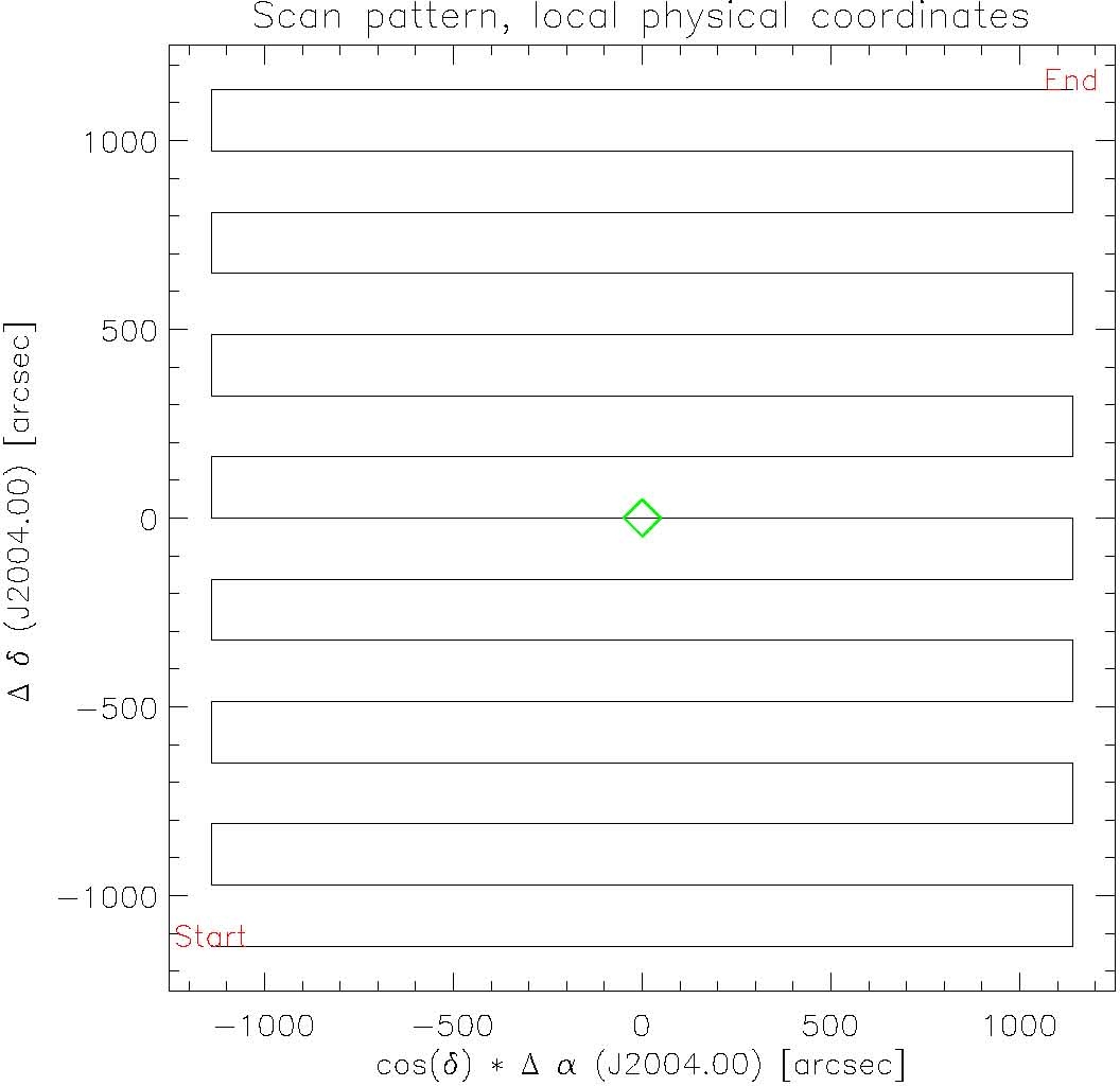
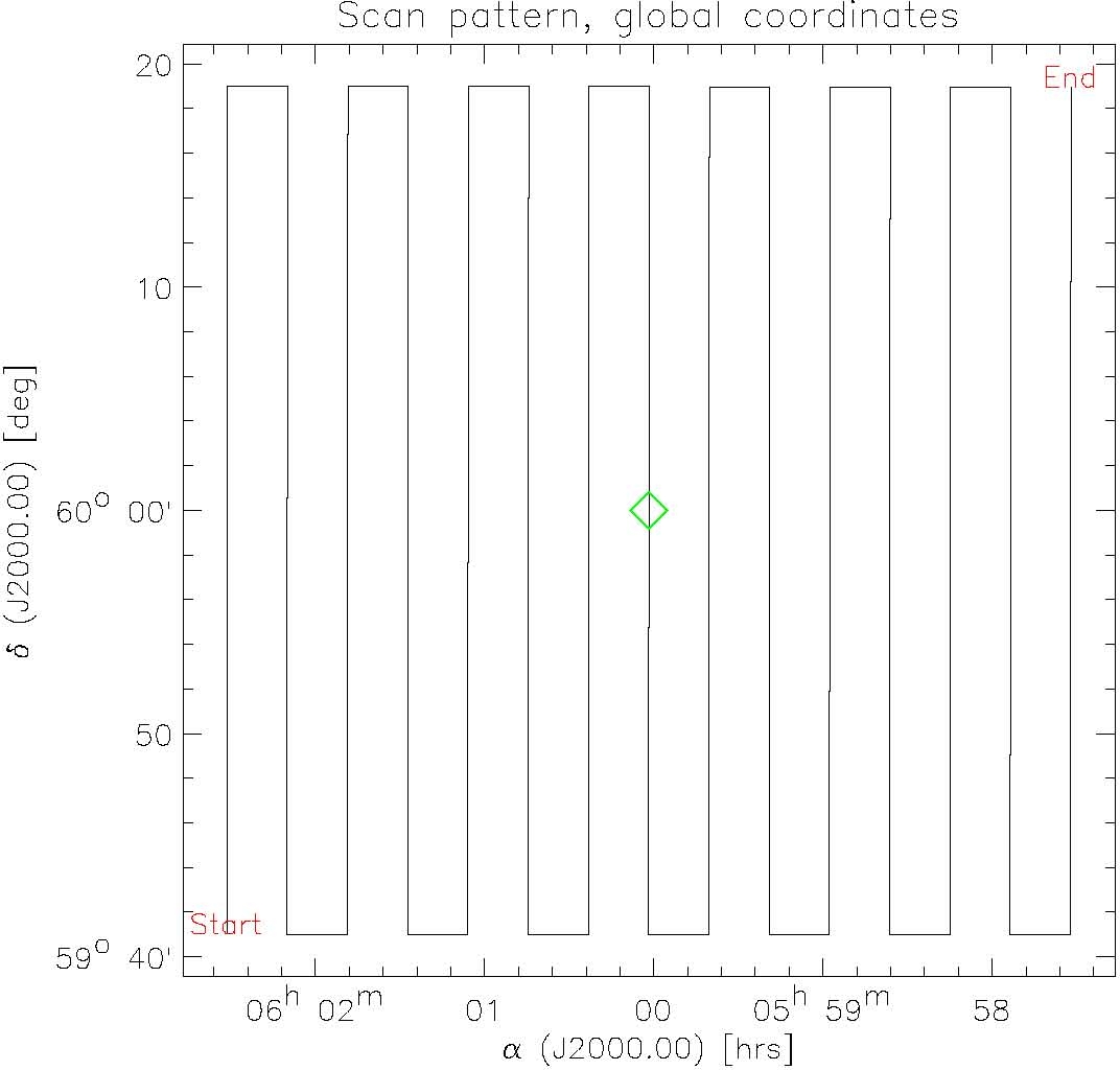
The above XRASTER_SCAN
command executes a single raster pattern in RA, dec coordinates:
The scan goes to larger RA and steps upward in declination. Note
that the scan is done in the equatorial system of date; this scan was
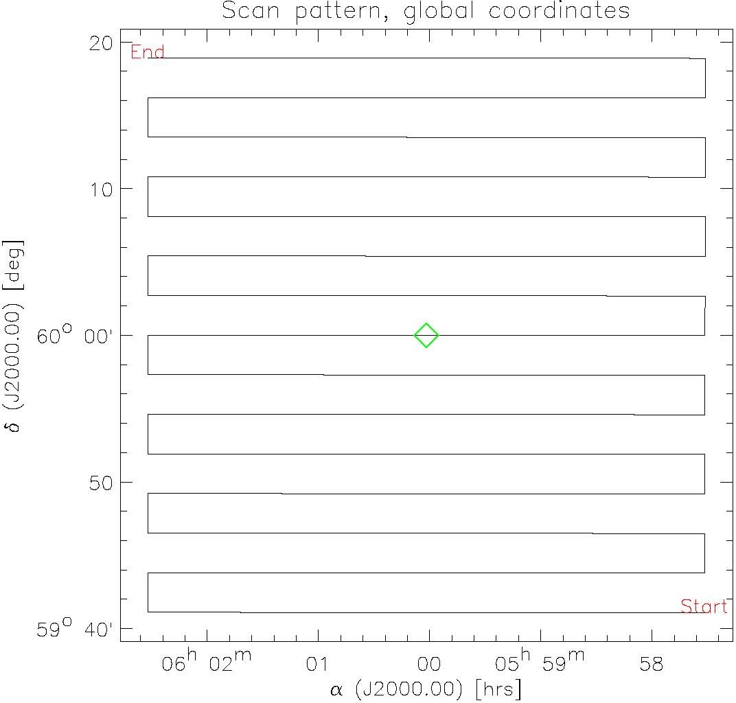
done on Jan 01, 2004, hence the epoch is 2004.0. When the scan is
plotted in a standard equatorial system (e.g., J2000.0), it comes out
differently:
The major difference is the apparent change in the horizontal
axis. This is due to the difference between "physical units" and
"coordinate units": since the object is assumed to be at 06h,+60d,
cosine(declination) = 0.5 and so 1 coordinate degree in RA only
corresponds to 0.5 physical degrees. Scans are always done in
physical units, so the RA coordinate axis appears expanded by a factor
of 2.
The minor difference is the barely noticeable tilt of the scans when
plotted in J2000.0. This is simply due to the slight precession
between J2000.0 and J2004.0.
Changing Scan
Direction or Coordinate System
You can scan in directions other than along RA. You can change
the angle of
the scans relative to the coordinate system using the /POSITION_ANGLE
qualifier. Position angle is measured from north through
east. /POSITION_ANGLE = 0
is a scan along the declination
direction, /POSITION_ANGLE = 90
is a scan along RA. The default value (i.e., if /POSITION_ANGLE is not
specified) is 90, as in
the above example.
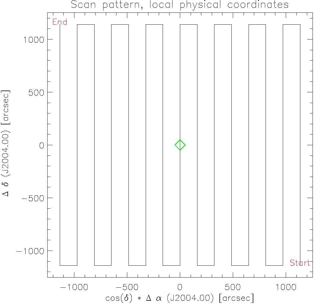
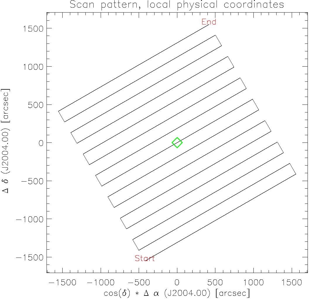
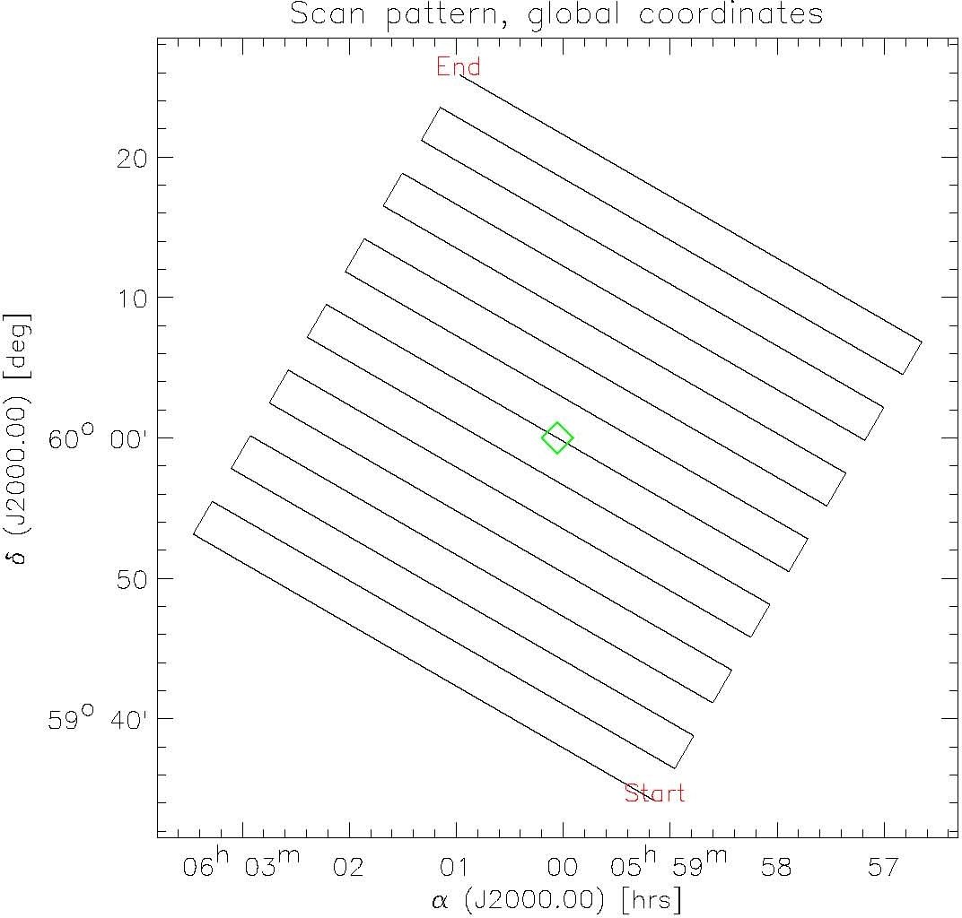
Some examples are given below; the left plot of each pair is the "scan"
coordinate system, the right plot is the "plot" or astronomical
coordinate system.
c
scan along RA
XRASTER_SCAN 120 2280 15 /STEP_SIZE = 162 /EQUATORIAL

    /ALTERNATE_DIRECTION /POSITION_ANGLE = 90
/SETTLING_TIME = 3
c scan along dec

XRASTER_SCAN 120 2280 15 /STEP_SIZE = 162 /EQUATORIAL

    /ALTERNATE_DIRECTION /POSITION_ANGLE = 0
c scan at 30 deg clockwise from a RA scan
XRASTER_SCAN 120 2280 15 /STEP_SIZE = 162 /EQUATORIAL

    /ALTERNATE_DIRECTION /POSITION_ANGLE = 60
/SETTLING_TIME = 3
Some notes on the scan polarity are
in order. The scan is first defined in a local system, with no
rotation, with the scan starting off by going to positive x. The
steps are done to positive y. Then the scan is rotated by 90 - /POSITION_ANGLE. The
rotation formula is forced by the definition of /POSITION_ANGLE, which
increases from north to east. So a /POSITION_ANGLE = 0 scan is one
from negative to positive declination, and a /POSITION_ANGLE
= 90 scan is one from
negative to positive right ascension. Note, however, that the /POSITION_ANGLE = 0 scan moves
from positive to negative right ascension on consecutive scans,
while the /POSITION_ANGLE = 90
scan moves from negative to positive declination on consecutive
scans. This inconsistency in step polarity in going from the
unrotated local system to the global system occurs because the /POSITION_ANGLE variable is
defined in a right-handed way but the astronomical coordinate system is
left-handed. Regardless, /POSITION_ANGLE
unambiguously defines the scan in global coordinates.
You can also do scans in the horizontal coordinate system; just replace
/EQUATORIAL with /ALTAZIMUTHAL. Note that, while UIP says the the /GALACTIC option is available fo XRASTER_SCAN, it does not actually work! In
either case,
scan lengths and position angles are in physical
arcseconds (not coordinate arcseconds). That is, when
plotting your desired coverage over an astronomical map, make sure to
take into account the necessary cos
declination or cos
elevation
factors so that you understand what the orientation and size of your
map will be. For further details, see XRASTER_SCAN in the CSO manual
(available on the main CSO page, http://www.cso.caltech.edu)
or consult Hiro Yoshida.
Our coverage simulation software (discussed below) can also calculate
the expected track for you.
Scan Angle and Dewar
Rotation and Obtaining Full Sampling
The Bolocam array does not
instantaneously provide full sampling of the sky. The array has a
hexagonal close-packed format, with pixels spaced by 38 arcsec.
The beam FWHM is 30 arcsec at 1.1 mm and 60 arcsec at 2.1 mm, so the
effective pixel spacing is 1.3 f lambda and 0.6 f lambda, respectively. Full
sampling requires a rectangular array with 0.5 f lambda pixel spacing, so clearly
instantaneous full sampling is not achieved.
However, one can rotate the dewar so that full sampling can be achieved
by scanning the array. The Bolocam dewar rotator performs the necessary
rotation in response to information received from the telescope.
The observer need provide no information, he must simply decide whether
dewar rotation is desirable or not. This section describes how
the dewar rotation angle is determined. The next section provides
software for calculating the expected coverage pattern. If you
don't want to think about the rotation angles, and just trust the
software, then you can skip down to here.
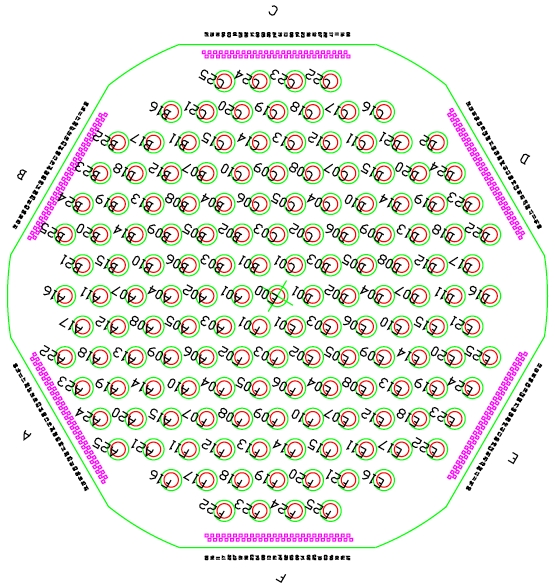
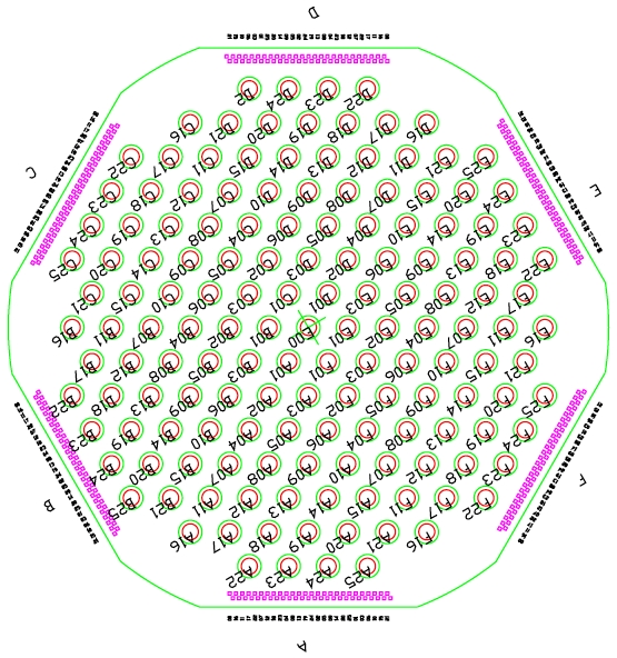
How Array Orientation
Affects Sampling
Full sampling can be achieved by
rotating the array relative to the scan direction. Full sampling
is achieved after one full pass of the
array across a line perpendicular to the scan direction, assuming that
the array has no missing elements. This is illustrated in the
following pictures, which show where various elements' centroids
cross the vertical line for a scans as 0, 10, 20, and 30 degrees
relative to the array rows for a toy 37-element array. Note how
much variation there is!
0 deg: 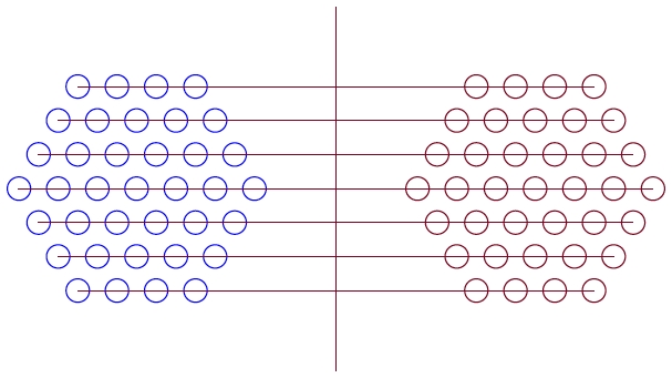
10 deg: 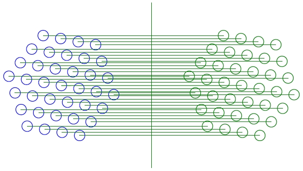
20
deg: 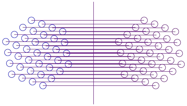
30
deg: 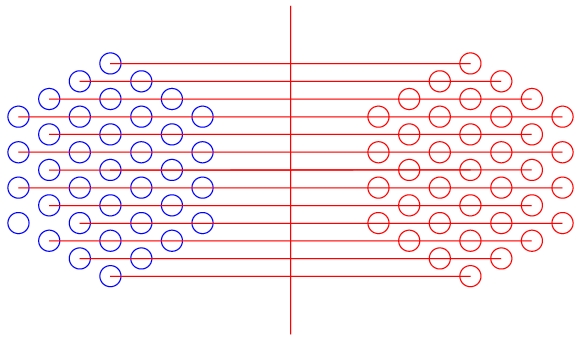
Important Coordinate
Systems and Angles
Now that we are beginning to talk
about rotation, it is necessary to be very clear about angles and how
they are defined. We have three coordinate systems to worry about:
- focal plane system: this
is the coordinate system one uses when looking at the focal plane from
the photon's perspective. Angles are measured in the standard
mathematical sense, counter-clockwise.
- sky system: due to the
way the optics transform the focal plane, the appearance on the sky of
the focal plane has the same handedness as its appearance in the focal
plane system. There is a 180 degree rotation of the array between
the two systems, but all angles continue to be measured
counter-clockwise. Some important notes regarding signs:
- The sky system naturally
coincides with the altazimuthal system: the sky system +x axis
coincides with positive azimuth and the sky system +y system coincides
with positive altitude.
- The sky system does not
coincide with the equatorial
system, because RA is measured "backward".
- The sky system's
definition of angles has the opposite sign asparallactic angle.
Parallactic angle is measured from the
+dec axis to the +el axis, with positive being counter-clockwise.
Sources in the southwest have a positive parallactic angle. That
is, in order to maintain a fixed orientation of the array on a source
as PA increases (the source moves west), the array must be rotated by a
negative angle in the sky system.
- rotator system: this is
the system that is natural for the person standing on the alidade
platform behind the dewar. Since one stands behind the dewar, one
sees the array from behind (opposite of "photon's eye view"). So
this system is mirror-inverted relative to the focal plane or sky
systems. Rotation
angles are positive when counter-clockwise in this system also,
therefore rotation angles in this system are the negative of their
value in the focal plane or sky system. That is, a positive angle in the rotator system yields
a negative angle in the sky or focal plane system.
Fortunately, angles in the rotator system effectively have the same
sign as parallactic angle, which (misleadingly) makes calculating
rotator angle for a given parallactic angle relatively easy.
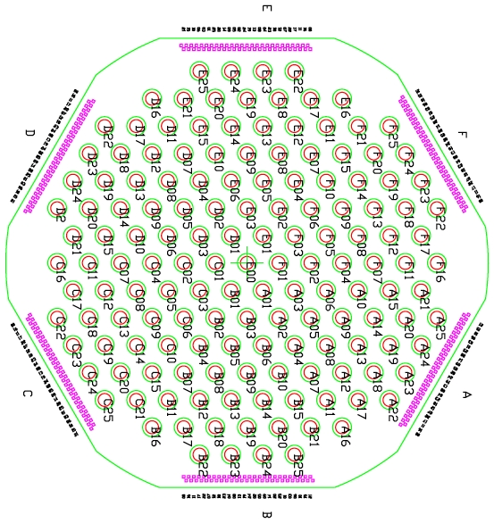
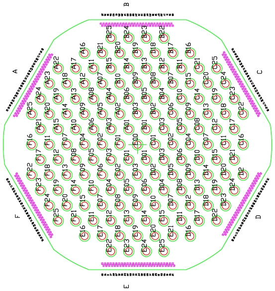
We define the following
angles. Refer to the array map given below, which is given in the
focal plane system.
- bolometer angle:
measured in the focal plane system, this is the angle from F01 to the
bolometer of interest. For example, E01 is at bolometer angle =
+60 deg. Since the orientation of the sky system is the same as
that of the focal plane system, the bolometer angle is valid in the sky
system also.
 array in focal plane system when array angle = 0
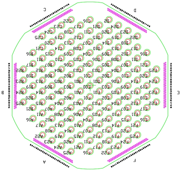
- array angle: this is the
angle of F01 measured in the sky system from the sky system +x axis
when the dewar is rotated to some arbitrary position. Recall that
the sky system is rotated from the focal plane system by 180 deg, so we
have
 array in sky system when array angle = 0
- fiducial angle: this is
the array angle (i.e., the angle of F01 measured in the sky system)
when the dewar rotator is
set to its nominal 0 position ("homed"). Due to the way we mount
the dewar, this is always approximately
+90 deg in
the focal plane system and -90 deg in the sky system.
array in sky system when homed (rotator
angle = 0)
- rotator angle: this is
the angle of the dewar rotator relative to the home position, measured
in the rotator system (i.e.
opposite sign convention to bolometer and fiducial angle)
- pixel offset angle: this
is the angle of a bolometer in the sky system from the sky system +x
axis when the dewar is rotated to some arbitrary position
- scan angle: this is the angle defined
by the /POSITION_ANGLE
parameter of the XRASTER_SCAN
command. The position angle is always measured counter-clockwise
from the +y axis of the coordinate system, counter-clockwise being
defined from the perspective of an observer on the earth looking up at
the sky.
- scan offset angle: this
is the angle by which we rotate the array relative to the scan angle to
get optimal sampling of the sky. We discuss below how this
optimal offset is determined; for now, take it as a given. It has
the same counter-clockwise sign convention as the sky system angle and
the scan angle. Since it is an increment to the scan angle, its
origin is not defined. In practice, what we do is calculate,
based on scan angle and the scan angle coordinate system, the array
angle needed to line the rows of the array up with the scan
angle. Then we increment array angle by scan offset angle, and
then calculate rotator angle from the incremented array angle.
The bolometer angle of a given bolometer is a fundamental constant of
the focal plane structure. The fiducial angle is set by the home
position and the optics (it is measured and then put into the
code). The rotator and array angles of course change when the
dewar is rotated. These angles are related as follows:
array
angle = fiducial angle - rotator angle
pixel offset angle = bolometer angle + array angle
= bolometer angle + fiducial angle - rotator angle
Converting Scan Angle
to Rotator Angle
When deciding on what angle to
rotate the array to, we determine array
angle from scan angle
and scan offset angle.
Suffice it to say that the array is first rotated so the array rows
line up with the scan direction as defined by scan angle and the coordinate
system, and then it is rotated by the additional scan offset angle.
- equatorial:
First,
convert scan angle from equatorial coordinates to altazimuthal
coordinates. Note the sign convention of parallactic angle is
opposite that of the /POSITION_ANGLE
parameter to the XRASTER_SCAN
command.
scan angle altaz = 90 + scan angle
equat - parallactic angle
This conversion accounts for all
subtleties of spherical geometry. Then calculate the optimal
array angle:
array angle = scan angle altaz + scan
offset angle
Then calculate the desired
rotator angle:
rotator angle = fiducial angle - array
angle
- altazimuthal:
Here,
we are already in altazimuthal coordinates, so we simply define
scan angle altaz = scan angle
and repeat the rest of the
equatorial version
Once we have the desired array angle, we can calculate
the rotator angle to
command as indicated above.
The Optimal Scan Offset Angle
and the Available Rotation Range
In the limit of a perfect
array -- one with no missing elements -- there is a 12-fold degeneracy
for the optimal scan offset angle.
Values of the angle that differ by 60 degrees are degenerate because of
the 6-fold symmetry of the array. Values of the angle that differ
by a sign are degenerate because of the mirror symmetry of the array.
Since we do have missing elements in the array, these degeneracies are
broken. So, in principle, one should optimize over the full 360
degree range for scan offset
angle. But, due to the way the rotator is set up and
operated, the available rotation range is 60 degrees, and the 60 degree
range is fixed in altazimuthal coordinates. This puts
restrictions on how well one can optimize the sampling at any given
time:
- The 60 degree altazimuthal rotation range that is available at
any time maps
onto equatorial coordinates in a time-dependent manner.
- This 60 degree altazimuthal rotation range does not rotate with
the desired
scan angle.
The end result is that one really
can only choose the scan offset
angle modulo 60 degrees at any given time. Moreover, the
scan offset angle is not easily changed by the user. So, we have
chosen a scan offset angle that gives the most uniform sampling when
averaged over the 6 positions that differ by 60 degrees. This scan offset angle is 10.7 deg,
measured counter-clockwise as indicated above. One gets sampling
that is almost as good with an angle of 4.5 deg.
For observers who care in detail what the orientation of the array on
the sky is at various rotator angles, we indicate below what the home,
maximum, and minimum rotator positions are in the sky system,
approximately. These pictures literally show what range of
orientations on the sky are available, so the observer can decide,
based on the commanded scan angle, what orientation the array will
rotate to. For example, to do an azimuth scan, the rotator will
rotate to array angle = (-120
deg + scan offset angle), which corresponds to rotator angle = +30 deg - scan offset
angle. This corresponds to rotating the array slightly counter-clockwise from the minimum array rotation angle
displayed below.
- When the rotator is set to its nominal home position (rotator angle = 0), the array
would appear on the sky approximately
as follows. The array
angle in this case is (approximately) -90
deg in the sky system and 90 deg in the focal plane system. If scan
angle altaz were a multiple of 60 deg (0, 60, 120, etc.), then
the scans would be along the rows of the array (approximately!).
array in sky system when homed (rotator angle = 0)
- The maximum rotator angle = +30 deg, which
corresponds to the minimum array
rotation angle available, array
angle = -120 deg in the sky system and array angle = 60 deg in the
focal plane system.
- The minimum rotator angle = -30
deg, which corresponds to the maximum
array
angle = -60 deg in the sky system and array angle = 120 deg in the
focal plane system.
Enabling Dewar
Rotation
It is trivial to use the dewar rotator; simply use the /ROTATOR_ADJUST keyword to the XRASTER_SCAN command.
There are two options for this keyword:
- /ROTATOR_ADJUST = ONCE
- /ROTATOR_ADJUST = ALWAYS
In general, Bolocam users will want to use the /ROTATOR_ADJUST
= ONCE version: this forces execution of dewar rotation
only once, before the start
of the first scan of the XRASTER_SCAN
command. Rotating the dewar at the end of every scan causes a
good deal of dead time and creates transients that are difficult to
remove, hence we advise against using the /ROTATOR_ADJUST = ALWAYS
version.
Designing Your Scan
Pattern and Calculating Expected
Coverage (esp. for Small Maps)
As the above discussion of dewar rotation indicates, the dewar rotator
will rotate the array so that full sampling is achieved by scanning the
array. However, the coverage from a single scan will still have
nonuniformities due to:
- Residual imperfect sampling. While every point on the sky
is hit by a beam when the array is rotated correctly, each beam has a
nonuniform response to the sky. This effect is minimized, but not
completely removed, by array rotation.
- Bad bolometers. Some bolometers in the array simply do not
work. Thus, even when scanning at the optimal angle, some regions
will see fewer bolometers pass by than other regions, so the coverage
will experience dips where bad bolometers pass.
For maps of regions large compared to the FOV and passed over many
times, it is relatively easy to smooth out the above nonuniformities by
offsetting the array on subsequent scans. For small maps, those
comparable to the FOV, or for fast observations where each sky pixel is
hit only a small number of times, this averaging fails and severe
nonuniformities may arise.
We find that the nonuniformity can be minimized if, after all your data
is in hand, the telescope boresight has scanned across your field in
steps of 26 arcsec relative to the scan direction. That is, if
you plot up the boresight motion on your map, integrated over all your
observations of the field, it would consist of a set of parallel lines
spaced out by 26 arcsec, each line with the same number of
passes. The 26 arcsec number is somewhat ad hoc; it was chosen
because it is a spacing that is achievable in a reasonable amount of
time. The smaller the spacing the better, though smaller spacings
resuls in proportionally larger macro execution times. However, because the optimal scan offset
angle is strongly dependent on the spacing (and this angle is not
changeable by observers), you should always use 26 arcsec or an
integral multiple thereof.
For small fields (comparable to the FOV), to achieve the above spacing
you can simply use /STEP_SIZE =
26. That is, your command will be something like
XRASTER_SCAN
120 960 39 /STEP_SIZE = 26 /ALTERNATE_DIRECTION /EQUATORIAL
/SETTLING_TIME = 3 /ROTATOR_ADJUST = ONCE
This command will move the telescope boresight over a region that is
960 arcmin x 988 arcmin (giving an approximately 480 arcsec x 508
arcsec good coverage region) with steps of 26 arcsec between
scans. The /ROTATOR_ADJUST
= ONCE
command indicates that the dewar should be rotated at the start of the
command (before the first scan starts). The command takes about
10 minutes to execute (8 seconds per step while scanning, 8-10 seconds
turnaround per step, and 38 total steps).
For large fields, we have found that it works well to use /STEP_SIZE = 156 (26 x 6 = 156)
and then to rotate through a set of 6 commands that each are offset in
the cross-scan direction by 26 arcsec. This yields the desired 26
arcsec step spacing after all 6 commands have been executed. For
example, a macro that moves the telescope boresight over a region that
is 4080 arcsec x 4056 arcsec (yielding a 3600 arcsec x 3576 arcsec good
coverage region, about 1 sq. deg.) could be the following:
FLSIGNAL 128 /RESET

STARE 1

FLSIGNAL 128 /SET
c vertical offset = - 2.5
* 26 arcsec
XRASTER_SCAN 120 4080 27 /STEP_SIZE = 156 /ALTERNATE_DIRECTION
/EQUATORIAL
/SETTLING_TIME
= 3 /ROTATOR_ADJUST =
ONCE /OFFSET = (-2040, -2093)
FLSIGNAL 128 /RESET

STARE 1

FLSIGNAL 128 /SET
XRASTER_SCAN 120 4080 27
/STEP_SIZE = 156 /ALTERNATE_DIRECTION /EQUATORIAL
/SETTLING_TIME
= 3 /ROTATOR_ADJUST
= ONCE /OFFSET = (-2040,
-2041)
FLSIGNAL 128 /RESET

STARE 1

FLSIGNAL 128 /SET
XRASTER_SCAN 120 4080 27
/STEP_SIZE = 156 /ALTERNATE_DIRECTION /EQUATORIAL
/SETTLING_TIME
= 3 /ROTATOR_ADJUST
= ONCE /OFFSET = (-2040,
-1989)
FLSIGNAL 128 /RESET

STARE 1

FLSIGNAL 128 /SET
XRASTER_SCAN 120 4080 27
/STEP_SIZE = 156 /ALTERNATE_DIRECTION /EQUATORIAL
/SETTLING_TIME
= 3 /ROTATOR_ADJUST
= ONCE /OFFSET = (-2040,
-2067)
FLSIGNAL 128 /RESET

STARE 1

FLSIGNAL 128 /SET
XRASTER_SCAN 120 4080 27
/STEP_SIZE = 156 /ALTERNATE_DIRECTION /EQUATORIAL
/SETTLING_TIME
= 3 /ROTATOR_ADJUST
= ONCE /OFFSET = (-2040,
-2015)
FLSIGNAL 128 /RESET

STARE 1

FLSIGNAL 128 /SET
XRASTER_SCAN 120 4080 27
/STEP_SIZE = 156 /ALTERNATE_DIRECTION /EQUATORIAL
/SETTLING_TIME
= 3 /ROTATOR_ADJUST
= ONCE /OFFSET = (-2040,
-1963)
The above set of commands yields the desired 26 arcsec spacing; but, by
doing it as six separate commands, rather than one large command, we
gain some advantages. First, each command (and hence observation)
is reasonably short, about 19 minutes (34 seconds scanning + 10 seconds
turnaround per step, 26 steps), so if the sequence needs to be
interrupted, one need only wait 19 minutes to finish the current
command. Second, since the array is only rotated at the start of
each command, the scheme forces the array angle to be updated once
every 19 minutes. If it were done as one large command, the array
angle would be updated once every 120 minutes. Over that long a
time, the field parallactic angle will change by a large amount and the
array rotation angle may become far from optimal.
The last comment brings up an additional important point in designing
observing macros. Macros that take a very long time can cause
significant problems. In addition to the variation in parallactic
angle over the execution of the macro, there are simple logistical
considerations. If something goes wrong in the middle of a long
macro, dealing with it can be difficult. If you restart the macro
from scratch, you will redo the region you have already covered,
resulting in a nonuniform coverage pattern. You can always try to
create a modified macro that restarts where the original macro died,
but that is prone to operator error. Another problem is that,
when the scan length becomes very long, the analysis software can slow
down considerably; all computations are at least linear in the scan
length, and fourier transforms require n log2 n
operations. The simplest way to avoid these problems is to break
up your macro into short (< 1 hr, preferably < 30 min)
pieces. When covering a very large field, this may simply mean
that you should attempt to cover the field with many small, square
observations rather than one large observation.
You can calculate your expected coverage pattern for each command using
a set of IDL routines we have written. These routines are
available as part of our software pipeline, which can be downloaded
using CVS. Directions for doing this are provided on the AnalysisSoftware page.
The main calculational routine, which you will call directly, is calc_track_cov.pro. It
generates the telescope track and coverage map for a single XRASTER_SCAN command (the
syntax is almost identical to the UIP command). calc_track_cov.pro has a long
documentation section at the start to explain how to run it. An
example calling syntax is given in the script run_coverage_code.pro.
You should run the calc_track_cov
routine with scan_offset_angle =
10.7 to match the aforementioned optimal scan offset angle; the
example script does this.
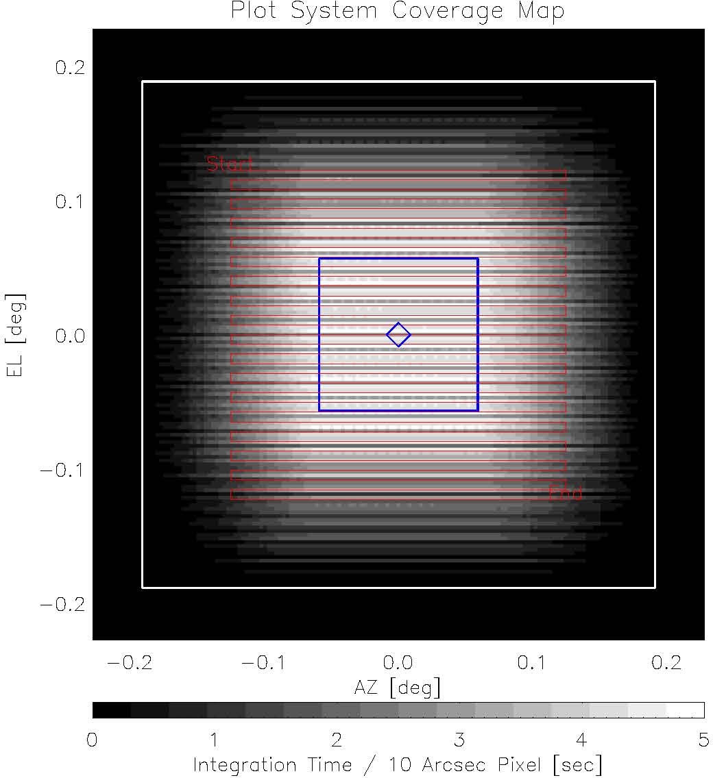
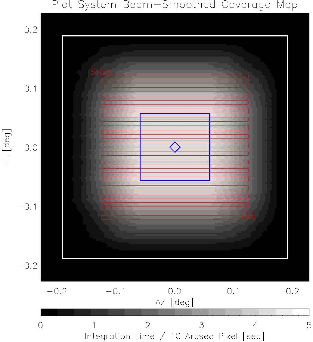
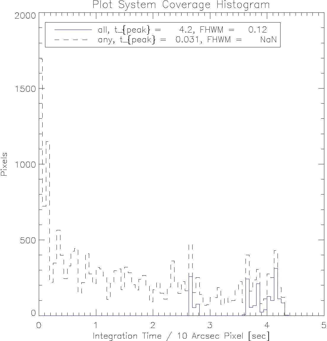
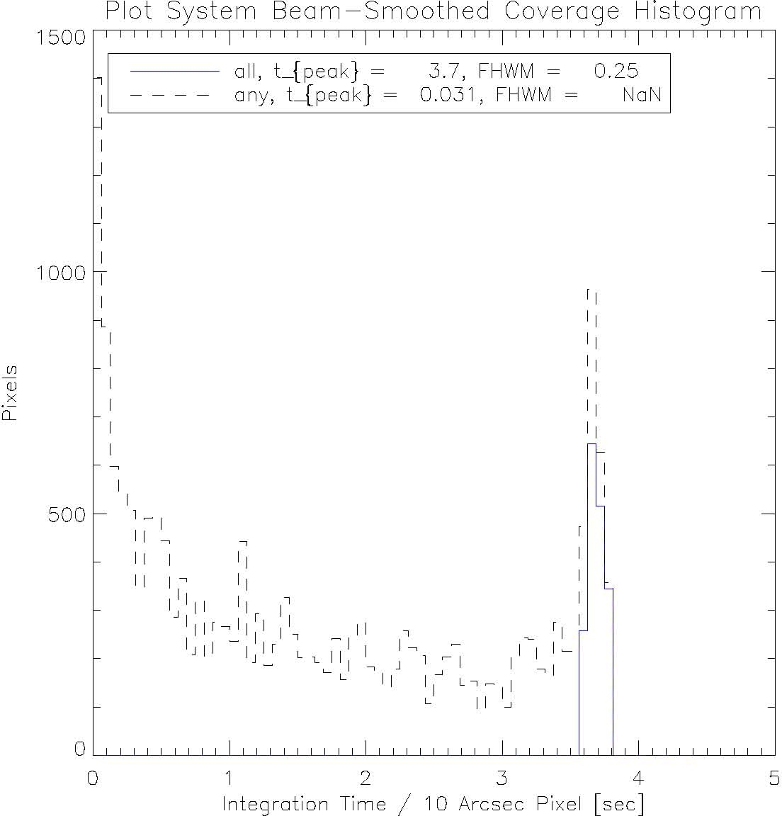
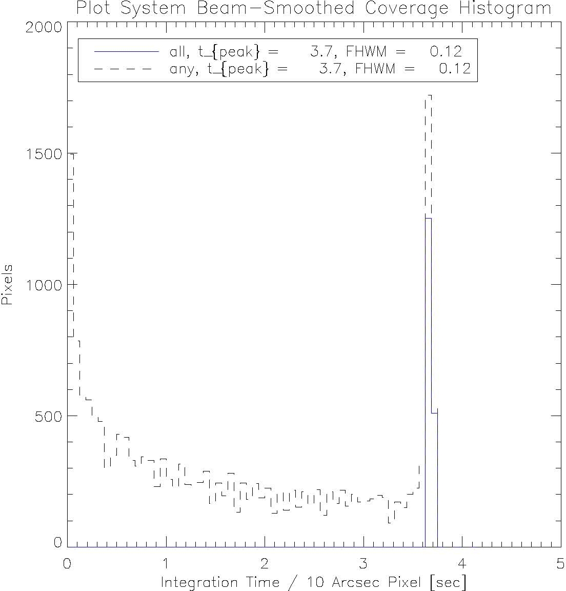
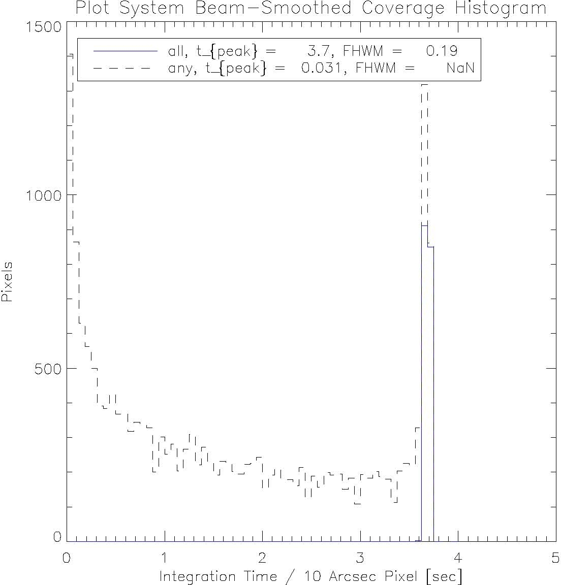
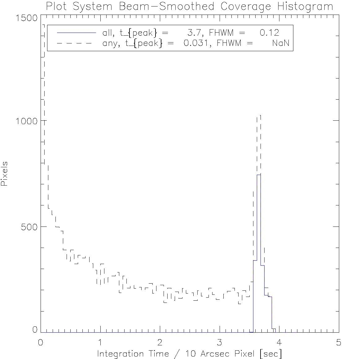
calc_track_cov will
generate
histograms of the integration time per pixel and coverage maps.
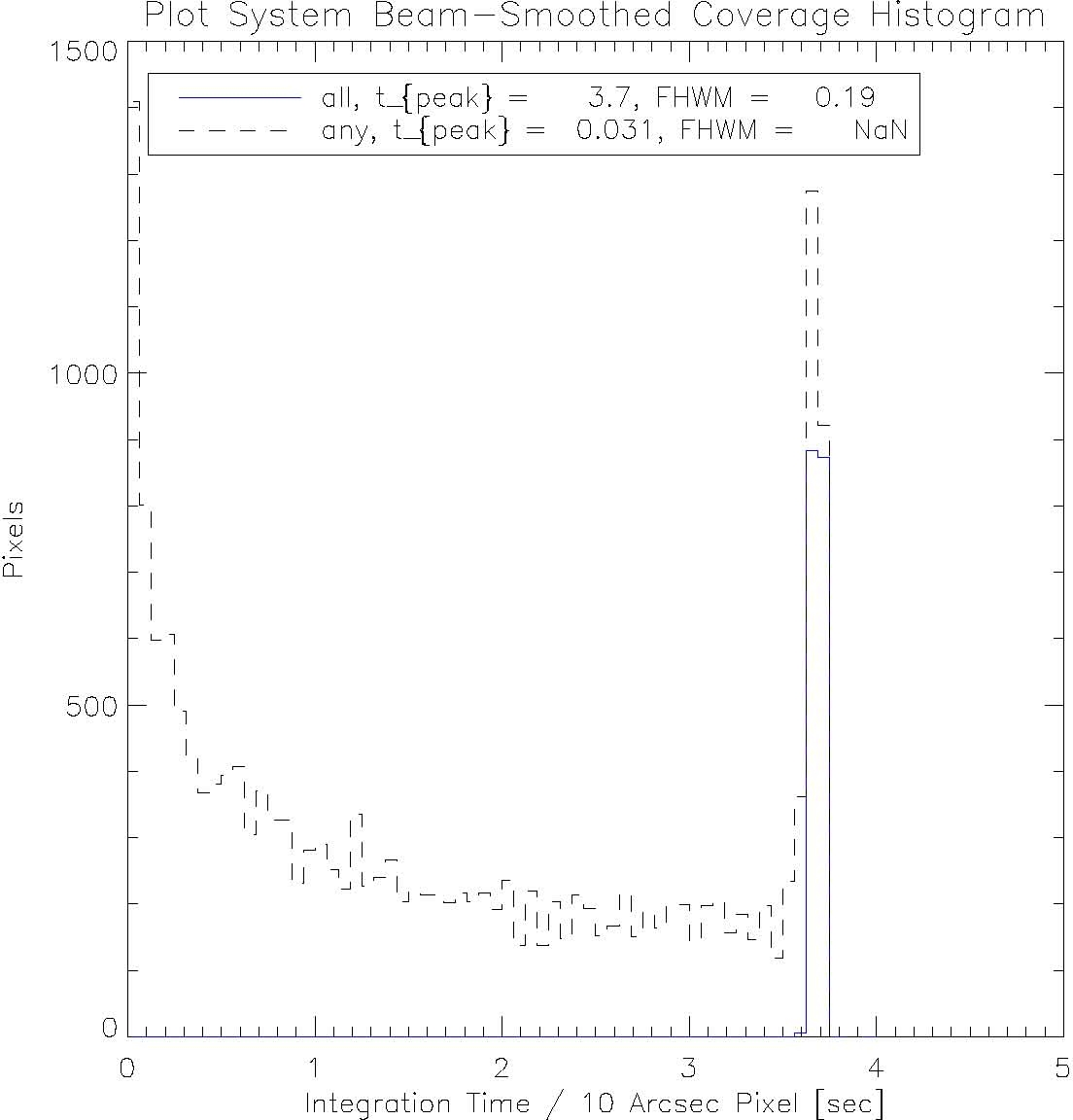
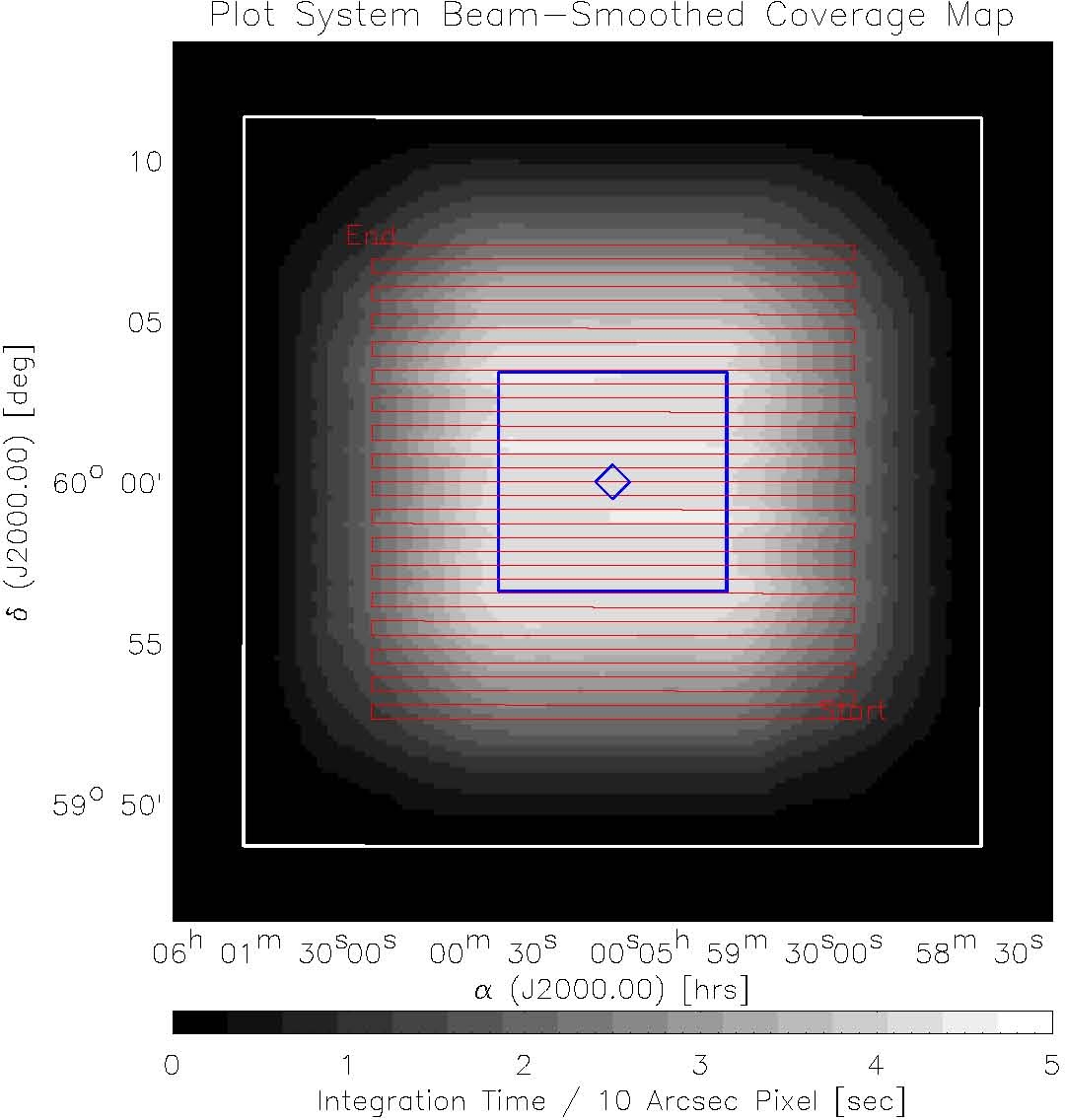
Both the histograms and coverage maps are provided in "raw" form (just
the number of hits per map pixel), and after beam-smoothing (smoothing
the coverage map with the beam to indicate the coverage on the
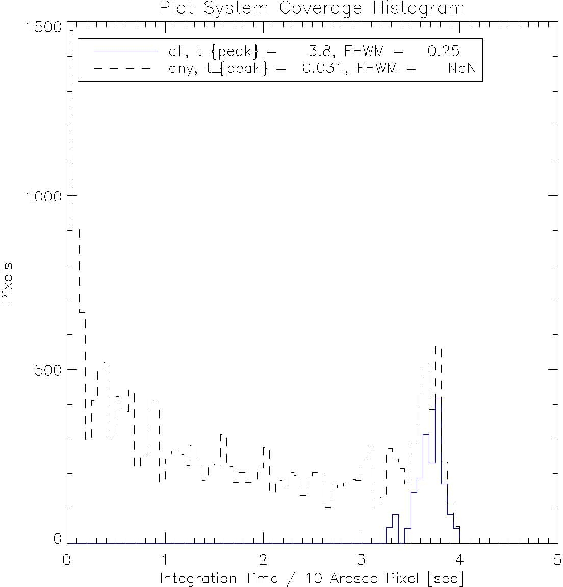
"astronomical" sky). Some example output is shown here:
- Plots of scans taken to optimize the scan offset angle. The
corresponding command would be
XRASTER_SCAN 120 900 35 /STEP_SIZE =
26 /ALTAZIMUTHAL /ALTERNATE_DIRECTION
/POSITION_ANGLE = 90 /SETTLING_TIME
= 3
The source position was fixed at (AZ, EL) = (0, 0) since this was only
a test to find the optimal rotation angle.
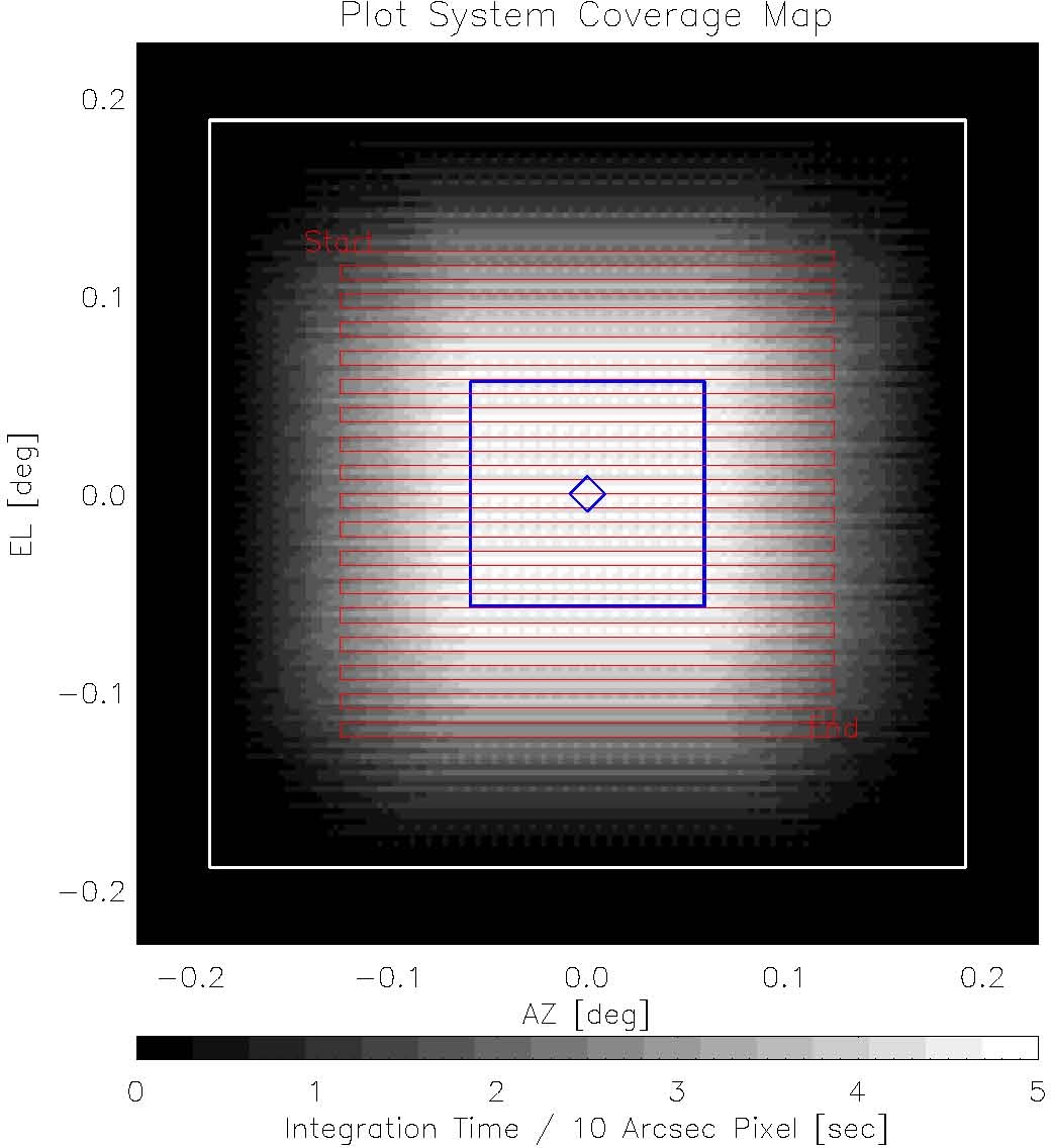
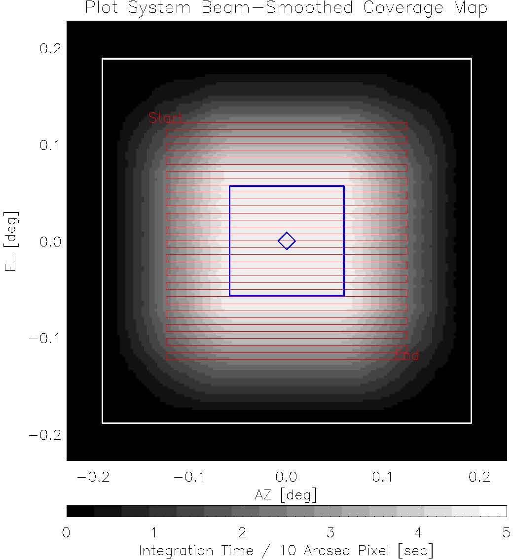
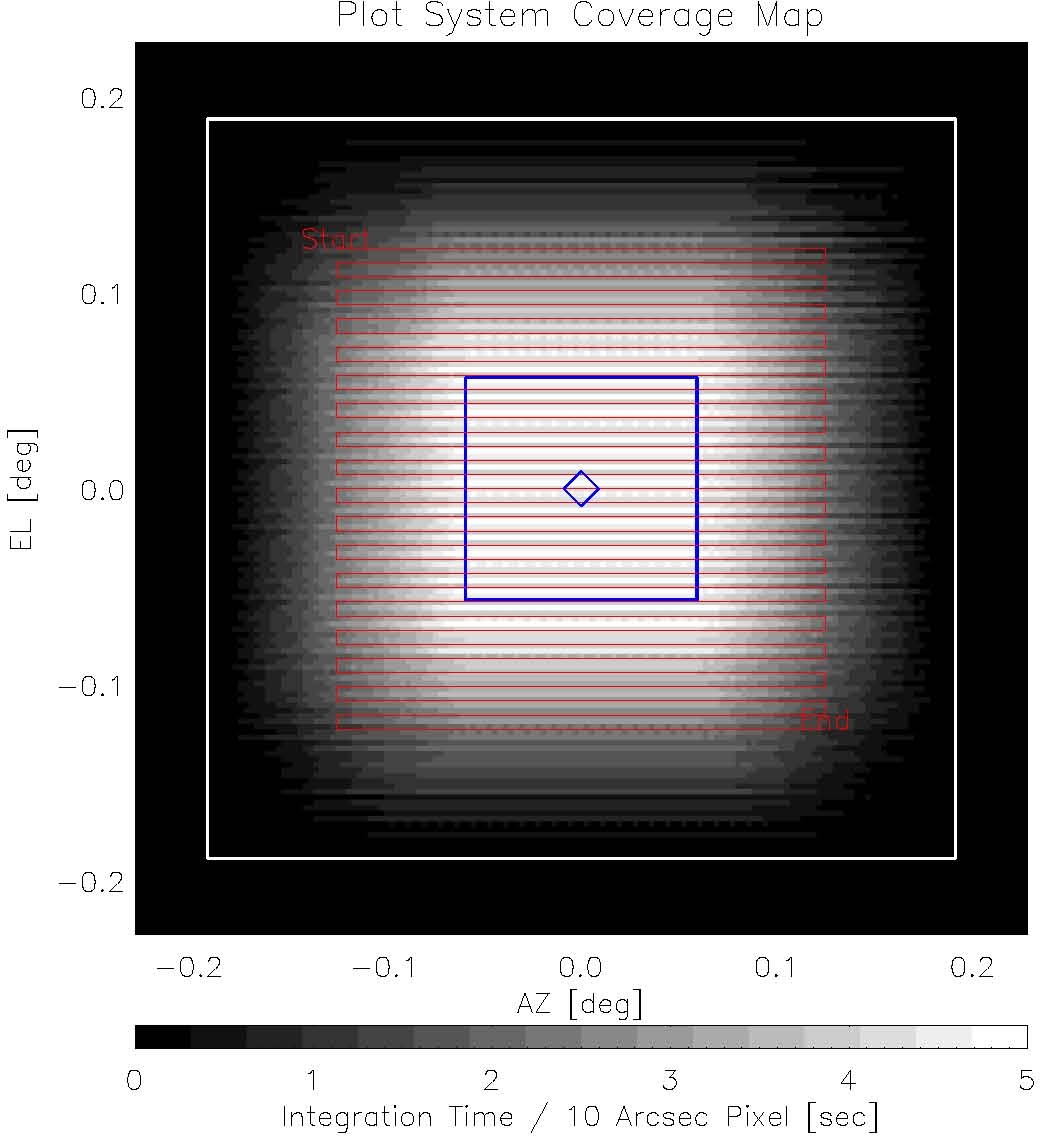
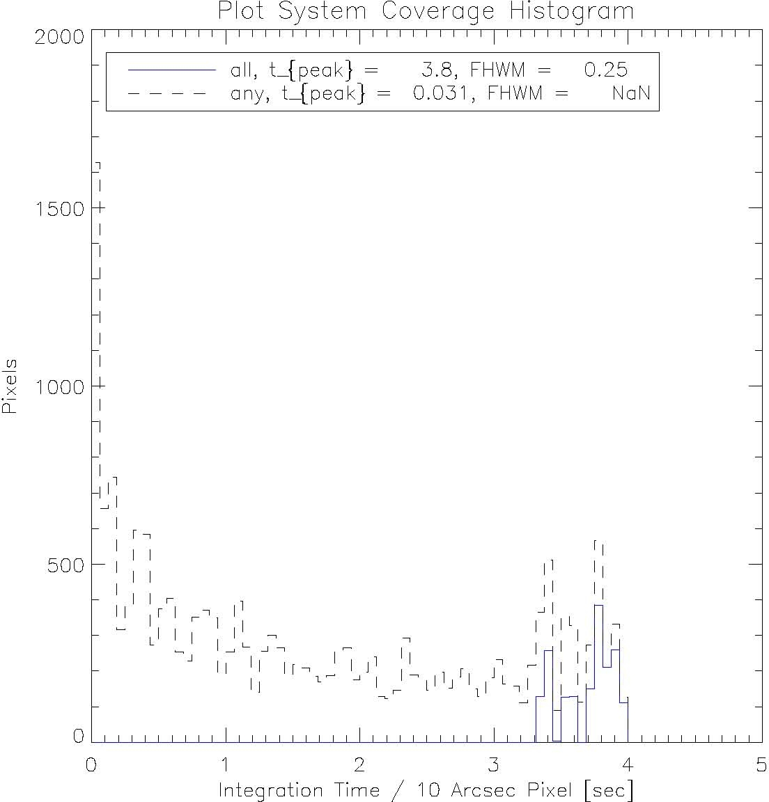
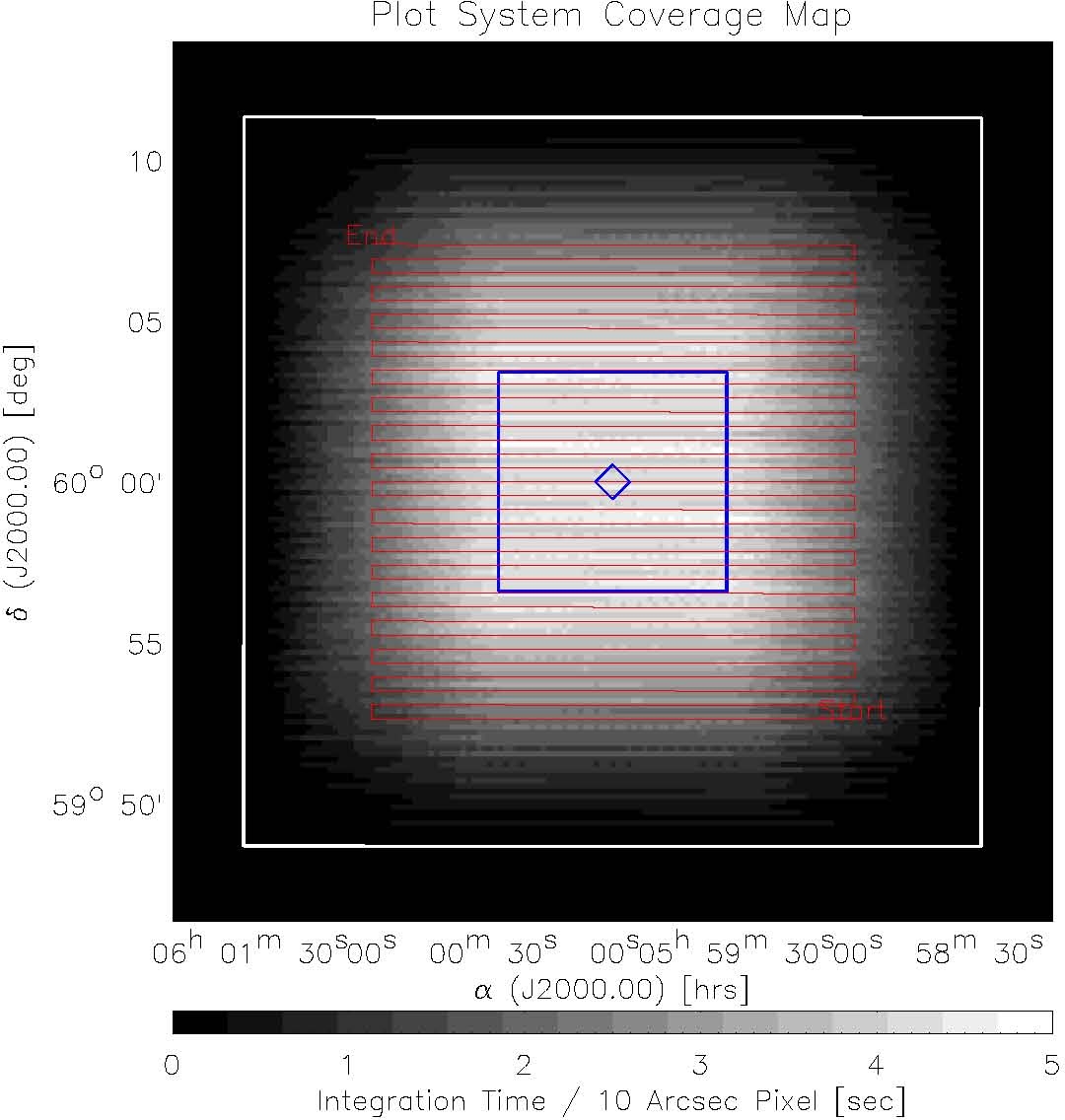
- First, we show an extremely bad case, setting scan_offset_angle = 0 deg so
that the rows of the array line up with the scan direction. The
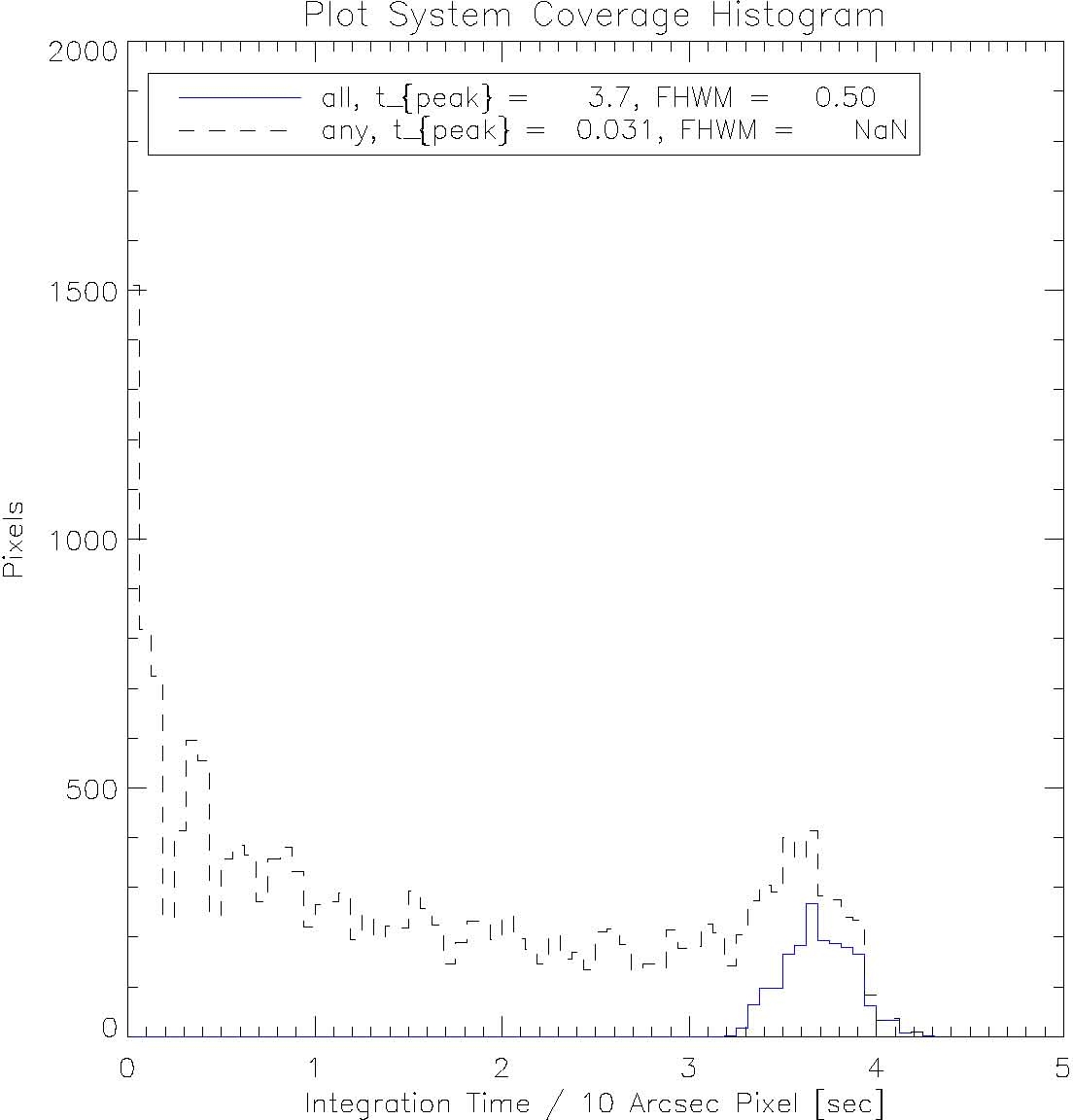
striping in the raw map is evident. This histograms that follow
show the poor coverage uniformity more dramatically. The
histogram to focus on is the blue (solid) one, which corresponds to the
blue square in the maps; this is the good-coverage
region, the part of the map that the array has fully passed over.
The other histogram (black, dashed) corresponds to the white square in
the map and is the any-coverage
region, roughly the area than some part (but not necessarily all) of
the array has hit. The good-coverage region is the region where
the coverage is pretty uniform because the entire array has passed
by. The red trace in the maps shows the path of the telescope
boresight and the blue diamond shows the source position.
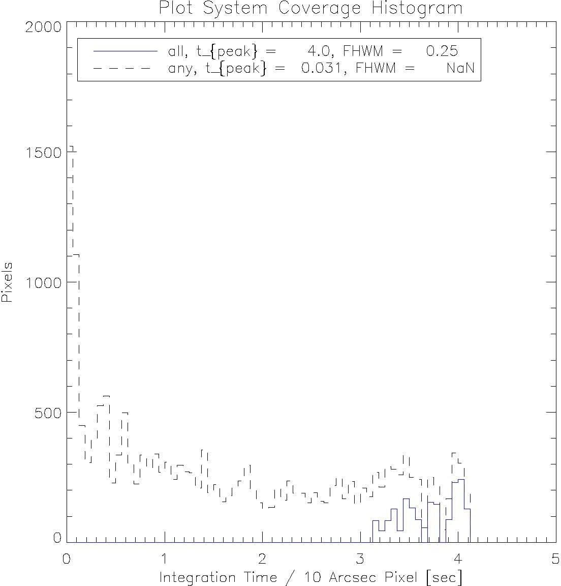
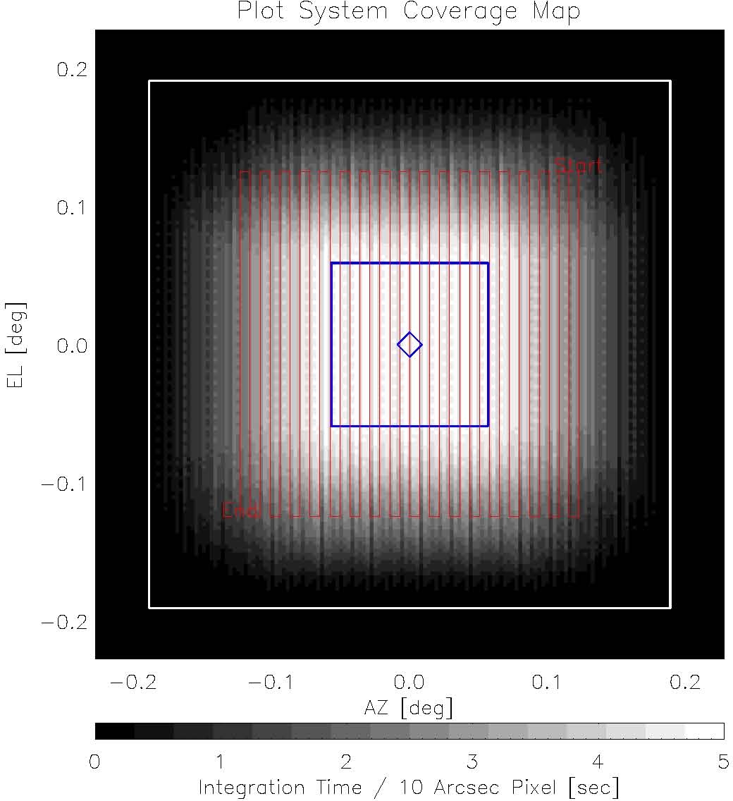
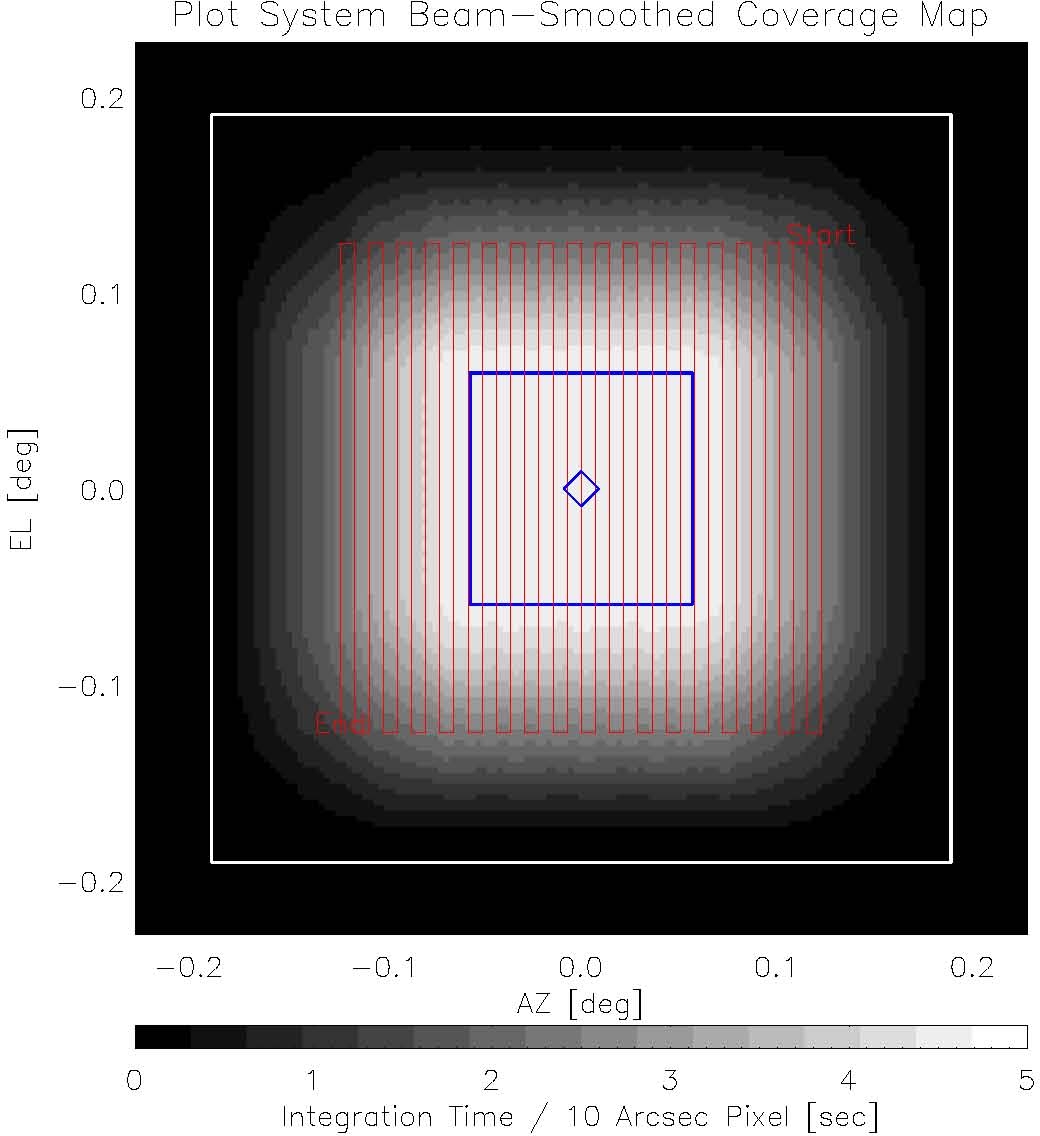
- Next, we show the coverage one gets when the optimal array
rotation angle is used, which is
scan_offset_angle = 10.7 deg as mentioned above. Note the
significant improvement in uniformity in the unsmoothed plots.
- Using scan_offset_angle
= 4.5 deg also works reasonably well:
- We also show a scan taken with /POSITION_ANGLE = 0 and scan_offset_angle = 10.7 deg.
Remember that, because the array can only rotate over a 60 degree range
(see the discussion of the rotator in the previous section), the
orientation of the array relative to the scan direction is different;
it is 60 degrees off from what it would be if we had simply rotated the
array by the 90 degrees that /POSITION_ANGLE
was changed by. The difference in coverage reflects the fact that
the bad bolometers are distributed nonuniformly across the array (the
array is not perfectly 6-fold symmetric). But the coverage
pattern variation is not much worse than in the /POSITION_ANGLE = 90 case, so
we live with it.
- A more realistic example is provided in the following, where we
show the coverage map found from performing the same scan geometry, but
doing it in equatorial units and on a source specified in equatorial
coordinates at (RA, dec) (J2000) = (6h, 60deg). The command used
was
XRASTER_SCAN 120 900 35 /STEP_SIZE =
26 /EQUATORIAL /ALTERNATE_DIRECTION
/POSITION_ANGLE = 90 /SETTLING_TIME
= 3
The scan angle in horizontal coordinates was 47.2 deg (parallactic
angle = 132.8 deg). The array was rotated to scan_offset_angle = 10.7 deg (i.e.,
10.7 deg counter-clockwise from the scan angle) and then shifted by
multiples of 60 deg to allow for the in situ -120 deg to -60 deg range
for array_angle, which
gave array_angle = -62.1 deg
(in altazimuthal coordinates).
Unfortunately, we have not yet written a routine that will add up the
results of many runs of calc_track_cov.
The coverage maps can be returned from calc_track_cov, so observers
should find it not too difficult to generate such a coadded coverage
map themselves.
Note that we have not included the cross-linked scans in the above
commands; each XRASTER_SCAN
command should have a cross-scan version, the best thing to do is to
interleave them.
Cross-Linking
A very important aspect of observing with Bolocam, or any scanning
instrument subject to 1/f or sky noise, is cross-linking. As explained
briefly on the Information for Proposers
page, the issue is that low frequency noise creates stripes in a
raster-scanned map, with the long axis of the stripes being along the
scan direction.
With a simple raster scan strategy without cross-linking, it is
impossible to remove the stripes without removing astronomical
structure -- essentially, there is not enough information in the
timestream to distinguish the 1/f or sky noise from large-scale
structure along the scan direction. Equally problematic is the
fact that there is no information about the relative DC levels of
consecutive stripes.
These problems can be dealt with by using a cross-linked scan strategy, one in
which each map pixel is observed with the array scanning in (at least)
two different directions through
the pixel. For example, consider a scan strategy that alternates
scans along RA and declination. The declination scans provide the
information needed to line up the DC levels of the RA scan, and vice
versa. The 1/f or sky noise is distributed in both
directions. These two features both allow registering of the
relative DC levels of adjacent rows as well as isotropizing the low
frequency noise. These affects will remove stripes at a cosmetic
level. Furthermore, with such a cross-linked scan strategy, on
optimal map-making algorithm can be used to deweight the low spatial
frequency information when it is corrupted by sky noise, but keep such
information when it is useful.
The conclusion to be draw from this discussion is that observers should
always cross-link their
maps. The most efficient way to do this is to define the area to
be mapped such that it is as close to square as possible.
Observing a long, thin region may be very inefficient in that the bulk
of the time will be spent turning around when doing the cross scans.
Calibration
Observations
As indicated on the Information for
Proposers page, frequent pointing observations and at least once
nightly flux calibration observations are necessary.
Pointing and Flux
Calibrator Catalogs
Positions and fluxes of calibrator sources are available from the JCMT
web site:
Realize that not all these sources are necessarily already entered in
the UIP catalogs (though all the planets are). Even if the source
is entered, it may not have the same name as given in the above JCMT
lists. You can use VERIFY
* /NEW to list all the sources in the catalogs you have opened
in
UIP; the sources are sorted by RA and declination, so you can search
for a source with known coordinates. The /NEW is necessary to get the
coordinates in J2000, which presumably is what most users will
want. See the earlier section that
discusses the catalog in detail. Certainly,
do not assume that, just because a source is in the catalog, it is
entered with the right coordinates! Verify all your source
coordinates, we make no claims that the catalog is 100% accurate except
in the case of planets.
Suggested Calibration
Schedule and Macros
The regimen we suggest is as follows:
- Pointing observations: It
is strongly suggested that
observers use multiple (2 to 3) pointing sources near the field to be
observed (within 10 to 20 deg), checking pointing once every 2 hours or
so, more frequently if near
zenith and the field's local coordinates are changing quickly.
The pointing sources should be spread out so that the pointing on the
field of interest can be interpolated, not extrapolated, from the
grid. Pointing sources with fluxes of 2 Jy and higher are easiest
to use, though lower-flux sources can be used if necessary. As
will be indicated below, only the center of the array need be scanned
across the source to check pointing, reducing the amount of time such
observations take. A typical macro for pointing calibration is
FLSIGNAL 128 /RESET

STARE 1

FLSIGNAL 128 /SET
XRASTER_SCAN 240 600
21 /STEP_SIZE = 11 /EQUATORIAL /ALTERNATE_DIRECTION
/SETTLING_TIME
= 3
The step size has been reduced a great deal because we need dense
sampling of the pointing source by a subset of bolometers to get good
pointing information. We do only need a subset of the bolometers
(the central 18 is enough), so the scan only covers 20 x 11 arcsec =
220 arcsec in the cross-scan direction. Depending on your scan
mode (/EQUATORIAL or /ALTAZIMUTHAL) and /POSITION_ANGLE setting for
your science fields, you may want to modify the above command; the
pointing scans should be done in the same coordinates and at
approximately the same angle as your science field data to ensure they
are applicable.
- Flux calibrations: These
are identical to pointing observations, except that the source should
be a primary or high-quality (esp. non-variable) secondary
calibrator. Again, only the center of the array need be scanned
over the source. You should hit at least one high-quality flux
calibrator per night.
- Full array beam maps:
These are essentially expanded pointing observations, scanning the
entire array over the source. It is preferred that a primary or
secondary calibrator be used so that the absolute flux calibration of
all array elements can be measured directly. These observations
are also used to measure the beam profiles. The typical macro for
this will be
FLSIGNAL 128 /RESET

STARE 1

FLSIGNAL 128 /SET
XRASTER_SCAN 240 800
73 /STEP_SIZE = 11 /ALTAZIMUTHAL /ALTERNATE_DIRECTION
/SETTLING_TIME = 3
The macro is longer in the scan direction and much longer in the
cross-scan direction (73 x 11 arcsec = 803 arcsec) to ensure the entire
array sees the source. Full
array beam maps should always be done in altazimuthal coordinates
because this is the system that we want to determine the beam shapes
in. Depending on the length of your run, you may or may not want
to do a full-array beam map. The decision should be based on when
the last such map was done. Contact the
Bolocam support person for help on deciding whether to do one.
Calibrating the Dewar
Rotator
Complications arise when using the dewar rotator. It is not
necessarily true that the center of the array and the dewar rotation
axis coincide. Therefore, dewar rotation may change your pointing
offset. At the current time, we do not have enough data to make
any concrete statements about the magnitude of this effect.
However, it is likely that this effect is relatively small compared to
the dependence on local coordinates and so it should be possible to
calibrate it out using the pointing observations. We are planning
tests at the start of the May, 2004, run and will provide more detailed
suggestions about pointing offsets and dewar rotation angle once those
data are in hand.
One general point can be made -- you probably should make the pointing
observation at the same dewar rotation angle as the last science
observation prior to the pointing observation. This can be
accomplished by simply not including any dewar rotation keywords in the
XRASTER_SCAN command for
the pointing observation; the dewar will remain at its current rotation
angle until a command is issued that uses one of these keywords.
The beam shapes and flux calibrations are certainly mildly dependent on
the dewar rotation angle because the angle affects the way the
different bolometers see the optics. Depending on how much you
care about the beam shape and absolute flux calibration, you may have
to take special care with these observations. Further details on
beam shape variation across the focal plane and from run to run
(between remountings of the dewar and optics) will be posted
here. If you have extreme flux and or beam shape precision
requirements, the best option is to not use the dewar rotator so that
the dewar rotation angle will stay fixed; consult with the Bolocam support person to establish
an observing program that will provide you with sufficiently stable and
well-measured beams and fluxes.
Revision History
- 2004/04/06 SG
First version
- 2004/04/12 SG
Much expanded
- 2004/04/18 SG
Add section on calculating coverage, add some example tracks and
coverage maps, add detailed macros for calibration.
- 2004/04/20 SG
Original tar.gz file of coverage code was missing a couple routines,
corrected version uploaded.
- 2004/04/23 SG
Add information on connecting to alpha1, adding sources to catalogs.
- 2004/04/29 SG
Add information on manpower and support staff.
- 2004/04/30 SG
Add backup program information.
- 2004/05/02 SG
Update backup program information.
- 2004/05/04 SG
Add /ROTATOR_ADJUST = ONCE command
- 2004/05/09 SG
Make note that /GALACTIC is not supported by XRASTER_SCAN, update
naming of coverage code archive
- 2004/05/21 SG
More explicit directions about editing macros via kilauea, warnings
about sources not being in the catalog or being there with incorrect
coordinates.
- 2004/06/20 SG
Remove separate archive for coverage code; link only to script
run_coverage_code.pro which is not in the archive.
- 2004/10/02 SG
Add warning about macros that take a very long time.
- 2005/01/25 SG
Post backup cut note and binomical_cl.pro routine.
- 2005/03/26 SG
Updated weather multiplexing section based on policy arrived at during
Feb/Mar 2005.
- 2005/06/05 SG
Update SCUBA calibration links.
- 2005/06/18 SG
Update SCUBA calibration links.
- 2005/12/09 SG
Correct example 6-offset scan macro -- y offsets were calculated incorrectly.
- 2006/05/05 SG
Replaced weather multiplexing discussion with link to official weather multiplexing policy page.
Questions or
comments?
Contact the Bolocam support person.