Data Acquisition, Rotator Control, and Data Handling
- Data Acquisition
- Inputs and Channel
Assignment
- Output Files
- Time Synchronization
- Where to find it
- Remote Access
- Rotator Control
- Data Streams
- Merging
- Details on what merge does
- Running merge in
standalone mode
- Necessary
configuration information
- Disk Cross-Mounting
and Soft Linking
- Revision History
Back to BolocamWebPage
Back to ExpertManual
Data Acquisition
Inputs and Channel
Assignment
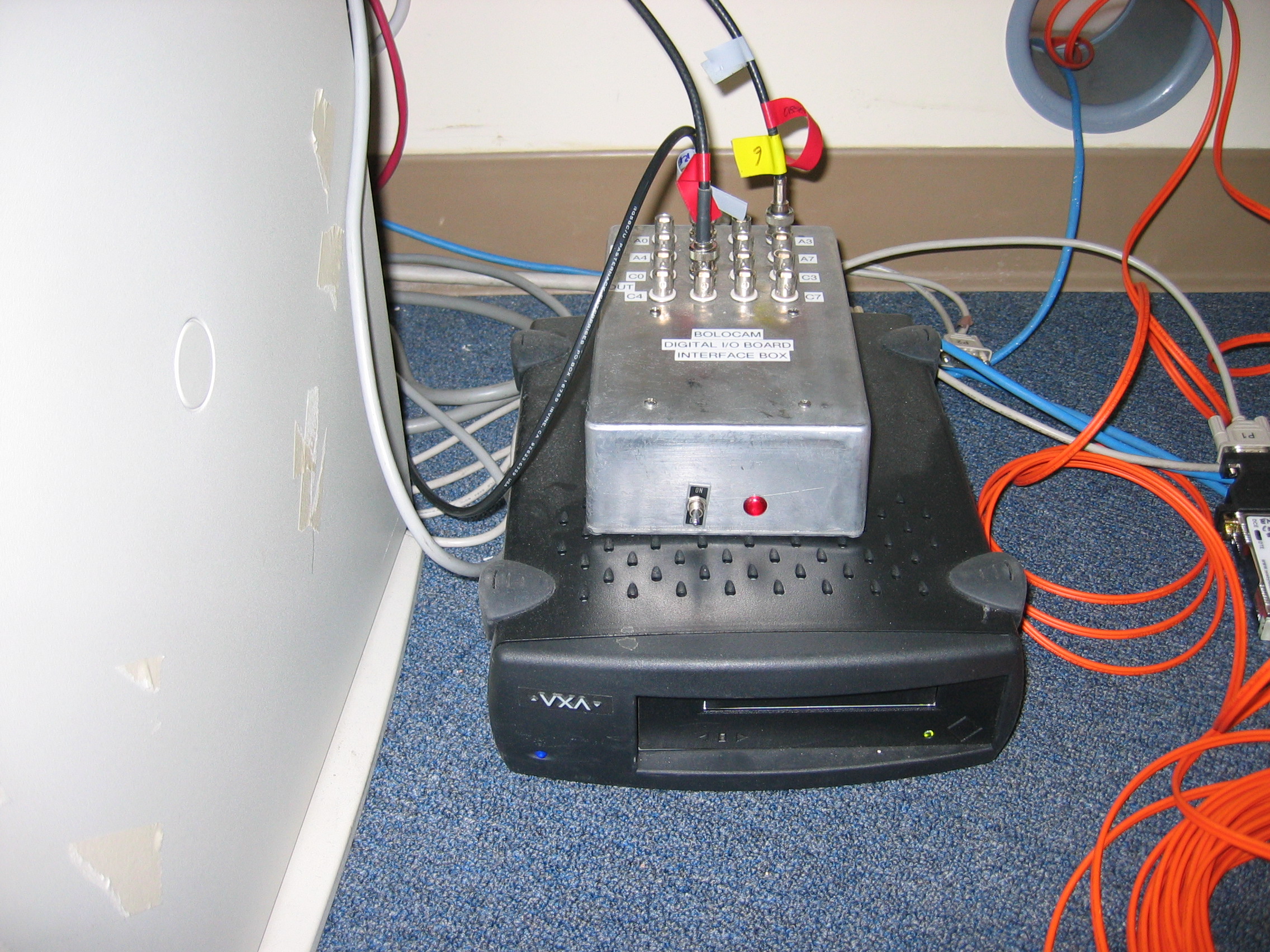
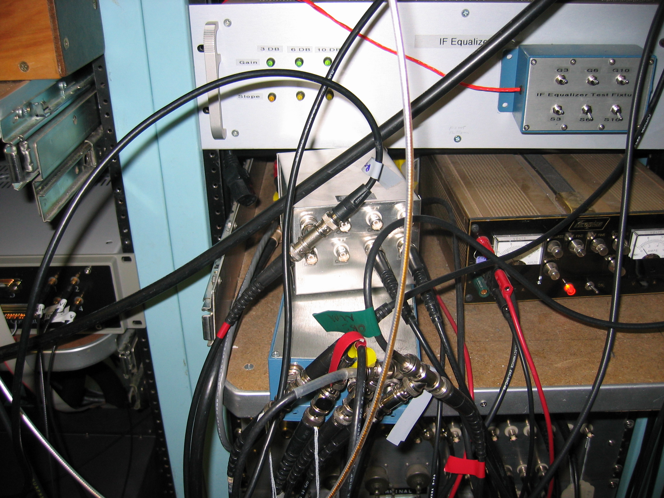
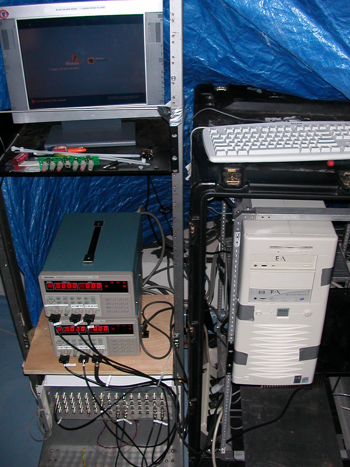
The bolometer data are acquired by a very simple Labview data
acquisition program that reads a multiplexed ADC. The SCXI
chassis in the DAS rack (obscured by cables
at the bottom of the picture) holds 12 multiplexer modules. Each
multiplexer module has
32 differential high-impedance inputs. The output side of the
multiplexers are connected via a cable to an ADC card inside the DAS computer (andante.submm.caltech.edu).
The ADC has 16-bit resolution.
The channels are numbered in sequential order. The 32 channels
read into the first (leftmost) multiplexer module are channels 0
through 31. The 32 channels in the second multiplexer module are
32 through 63. And so on. The 32 channels in the last
(rightmost) module are 320 through 383. The multiplexers map to
hextants in the following order, note that each hextant only uses the
first 24 channels of each multiplexer bank:
MUX module 1 DAS ch. 0 - 23
hextant 1 AC lockin
2 32
- 55 hextant 1 DC lockin
3 64
- 87 hextant 2 AC lockin
4 96 - 119
hextant 2 DC lockin
5 128 - 151
hextant 3 AC lockin
6 160 - 183
hextant 3 DC lockin
7 192 - 215
hextant 4 AC lockin
8 224 - 247
hextant 4 DC lockin
9 256 - 279
hextant 5 AC lockin
10 288 - 311
hextant 5 DC lockin
11 320 - 343
hextant 6 AC lockin
12 352 - 375
hextant 6 DC lockin
The general DAS channels table can be found here . The wiring table provided in the black Bolocam documentation binder
(and also
available here) shows which
bolometers go to which DAS channels (relative to the start of each
multiplexer bank). The pattern repeats for each hextant and for
AC and DC lockin outputs.
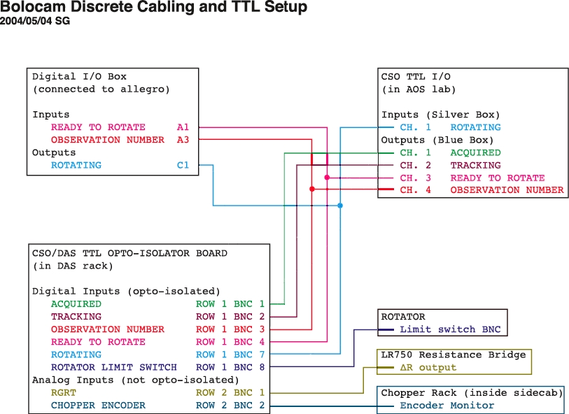
The remaining 8 channels of each module are free. These
additional channels are only used in modules 1, 2, 11, and 12:
MUX module 1 DAS
ch. 24 ACQUIRED
1 25
TRACKING
1 26
OBSERVATION NUMBER
1 27
READY_TO_ROTATE
1 28
- 29 not used
1 30
ROTATING
1 31
ROTATOR LIMIT SWITCH
(typically not plugged in)
2 56
RGRT
2 57
CHOPPER ENCODER
2 58
- 63 not used
11
344 Lockin
reference AC lockin
11 345 -
350 hextants 1 - 6 bias AC lockin
11 351
not used
12 376
Lockin reference DC
lockin
12
377 - 382
hextants 1 - 6 bias DC lockin
12 383
not used
Output Files
The program writes a simple binary file format. There are 2 bytes
per digitized voltage and 384 channels, so 768 bytes per time
sample. We sample at 50 Hz, giving 37.5 kB/sec. A new file
is written every minute, so each file is 2.25 MB long. Each file
has a simple header describing the data, which is not used
anywhere. Rather, we rely on the above known cabling scheme to
determine which signals are being read into which multiplexer channels.
During normal data-taking, the files must be written to the directory D:\DAS_DATA\YYYYMMDD. We
cross-mount this directory to allegro
and it is assumed the files for a given UT day are in the YYYYMMDD subdirectory. If
you are just testing the DAS, you can write the files anywhere you like.
The DAS program will stop with an error message if the desired output
directory does not exist or if there is no free space on the output
disk. It will warn you but allow you to continue if there is less
than 1 GB of free space on the output disk.
Time Synchronization
We use network time protocol (NTP) and the Windows time service (w32tm) to keep andante's clock close to a time
standard. Our analysis software can deal with small drifts (up to
a few seconds), but larger drifts can cause serious problems. So
we have set the computer up to time synchronize once per day. The
observer checks the time synchronization and forces it to resynchronize
prior to beginning observing. Instructions for resynchronization
are given in the Daily Observing
Tasks startup instructions.
Where to find it
The most recent version of the program is run by startDAS and can be found in andante in the directory C:\Documents and Settings\Bolocam\My Documents\Labview vi\DAS. Multiple versions usually exist, reflecting minor
changes and
updates. They are all titled BCAM_DAS_YYYYMMDD to reflect
the revision date. The desktop shortcut should point to the most
recent version. The BCAM_DAS_YYYYMMDD_AUTO is the vi called by the DAS startup program.
Be sure to not accidentally start BCAM_DAS_ASCII, which is only
used for instrument testing by the instrument team!
Remote Access
One can gain remote access to andante
using Microsoft Remote Desktop Connection. You can run the
software from the computer room PC (iha.submm.caltech.edu) or from your own computer, as follows:
- Any Windows XP system has Microsoft Remote Desktop Connection
already installed. Go to Start
-> Accessories -> Communications -> Remote Desktop Connection.
- If you have an older edition of Windows, or a Mac, you can
download the client from Microsoft. Just go to http://www.microsoft.com and
search for "Remote Desktop Connection" to find a download page.
The software is free. If you have a Mac, include "Mac" in your
search.
- RedHat Linux (which runs on champinux):
download rdesktop
from http://www.rdesktop.org/.
- Fedora: from the menu select >Internet > Terminal Client Server. Note: krdc tends to fail.
- SuSE Linux (which runs on kilauea,
puuoo, allegro, and the desktop in HP CSO office): Comes with the
Konqueror desktop environment. Just type krdc & at a shell prompt.
For any of the above linux environment, the syntax in the host field is: The syntax is rdp:/andante.submm.caltech.edu
Once you have your remote desktop client installed and started, connect
to andante.submm.caltech.edu.
(You may have to precede this with rdp:/ to advise your client as
to the protocol to use.) At the Windows login screen, use the
usual bolocam username
and password
(available in the white Bolocam Manual binder).
Some notes and tips:
- Only one person at a time can access andante; if a new
remote access user connects, then the current user will be kicked
off. Even if the current user is logged in locally, he will be
logged out.
- The viewer has a Full
Screen option that may be useful.
- The default color options on the client may be set for minimum
color information (maximum speed); you can increase the color
information being transmitted to get a nicer display.
- The remote desktop server on andante automatically starts
when Windows begins, so you can restart the
machine using the remote client and log back in after the computer has
rebooted.
Rotator Control
The dewar rotator rotates the dewar prior to an observation to optimize
the sampling of the sky. It has been found that the best sampling
is achieved when the dewar is rotated such that the rows of the array
make a 10.7 degree angle with the scan direction.
Installation and cabling of the dewar rotator is described on the Setting up for
Observing
page. Details on cabling and checking the DIP switch settings are
also provided there. Detailed information on the motor
controller, motor encoder, and
fiber-optic isolators is found on the Bolocam internal web site on the Rotator
page (also accessible from the ElectronicsAndWiring
page). Here we described how the rotator operates.
Here are two useful picture, double-click on them to get larger
versions:
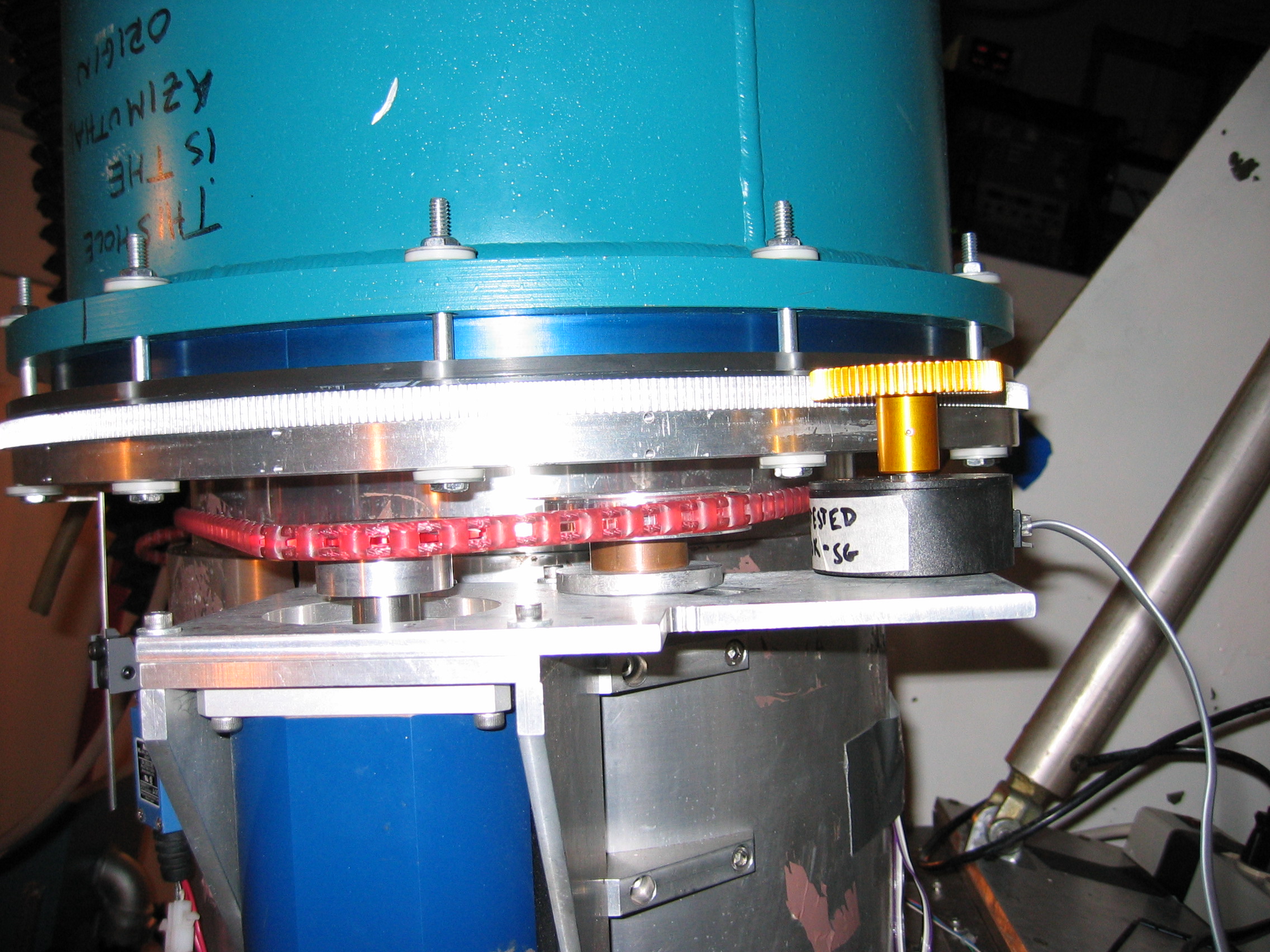
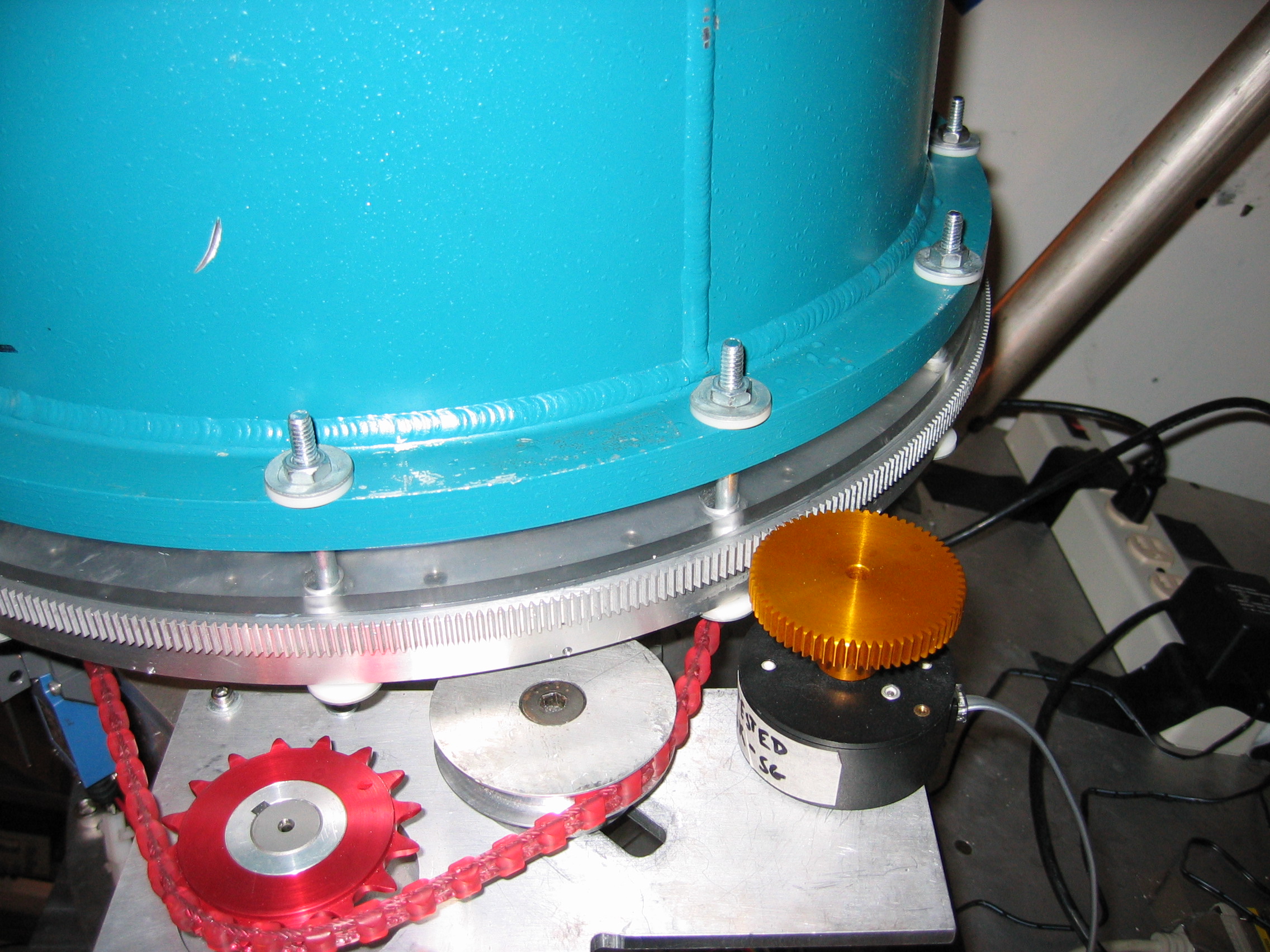
The rotator is driven by a motor that mounts to its side. The
motor is the blue cylinder seen in the pictures. It mounts to the
fixed part of the rotator and drives a red belt that connects to the
rotating part of the rotator. The red belt is held on by two
clamps, seen in the third picture. There is slack in the
belt. Most of the slack is
taken up in a loop between the two clamps. The remaining slack is
present on the drive side of the belt and is taken up by the slideable
pulley seen in the second picture.
The rotator position is read by a geared encoder, seen in the second
picture. A large gear is
screwed to the rotator flange itself. A small gear meshes with
the large gear and is attached to the shaft of an optical
encoder. The encoder is mounted
to the same plate as the pulley. The large gear has 512 teeth and
the small gear 64 teeth, so one full turn of the encoder corresponds to
45 degree rotation of the rotator and one tooth of the encoder
corresponds to 0.7 degree rotation of the rotator. There is some
play between the two gears to prevent them from binding; this play
yields about 0.1 degree uncertainty in the rotator angle.
Communication with the rotator motor and encoder are by RS232 serial
protocol. allegro
is the controlling computer; it has a multiport serial port card.
Communication is via two pairs of fiber optic lines, seen in closeup here. The motor has its own shaft
encoder, so a position is commanded by
first commanding the rotator to move close to the desired position
based on its own shaft encoder, and then the encoder is used to measure
the rotator position and further commands issued to the motor to
improve the accuracy of the positioning.
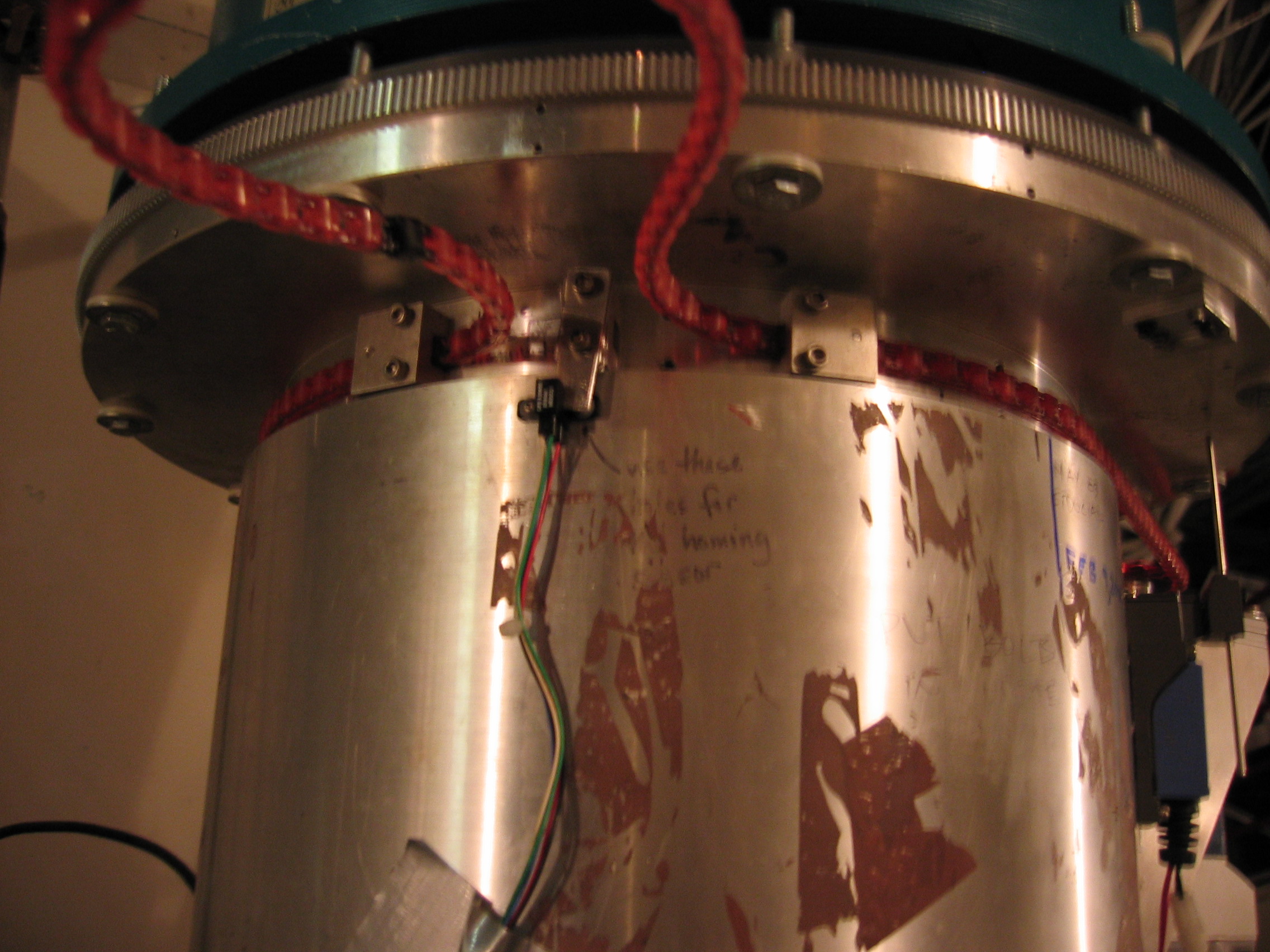
The rotator has a homing sensor that is used to define the encoder
origins, seen in the third picture above. The homing sensor
consists of a small IR sensor that is mounted to the nonrotating
base of the rotator; it is the small black plastic piece with the wires
coming from it. A homing tabis mounted to the rotating part and
sticks down so that it passes
through the IR sensor. When a home command is issued to the
motor, the motor rotates the rotator (clockwise as seen from above)
until the homing tab occludes the IR sensor. The motor encoder
origin is set to be this point. The rotator encoder is also
zeroed at this point. When the dewar is mounted to the rotator in
the correct orientation, the e-box points about 24 degrees clockwise
from due
right (over the motor) when the rotator is homed. The rotator
motor needs to be homed once after mounting the dewar on the
rotator. The only other time you should need to home the dewar is
if the limit switch is hit. The
home position is your zero-point reference -- it is very important that
you do not tweak or move the homing tab unless you want to recalibrate
the rotator!
The rotator has a limit switch.
Tabs on the bottom of the rotator
flange hit the limit switch if the rotator goes too far in either
direction. "Too far" is defined to be "getting too close to the
clamp points of the belt". When the limit switch is hit, the
motor power is cut and the dewar will tend to rotate back so the e-box
points straight down. This is no great tragedy, but you will need
to re-home the rotator after cycling the motor power. You will
likely never hit the limit switch in the clockwise direction, but the
limit switch in the counter-clockwise direction is just past the normal
rotation range used during observing, so be forewarned.
During normal operation, the rotator control program makes use of the
6-fold symmetry of the array and restricts the rotator motion to a
range of 60 degrees around the home position, with the upper end of the
motion allowing the e-box to point due right over the motor.
The following programs are used to control the rotator. They can
be run from the observer
account on allegro.submm.caltech.edu:
The source code for these programs sits in allegro:/home/observer/src.
If you for some reason need to modify one of these programs, be sure to
save the previous version in the appropriate subdirectory of the archive/ subdirectory.
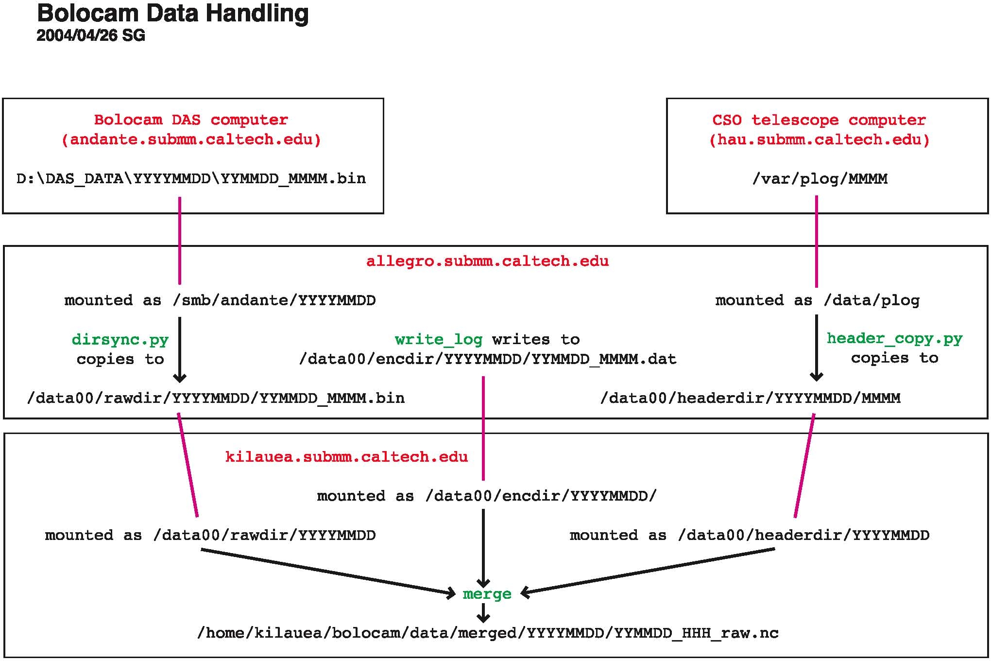
Data Streams
The data flow for Bolocam is illustrated in the following picture:
There are 3 data streams coming from 3 different places:
- bolometer timestreams:
digitized by the multiplexer bank/ADC card
associated with andante.submm.caltech.edu
(the PC in the electronics rack
on the third floor) and written
to its local disk.
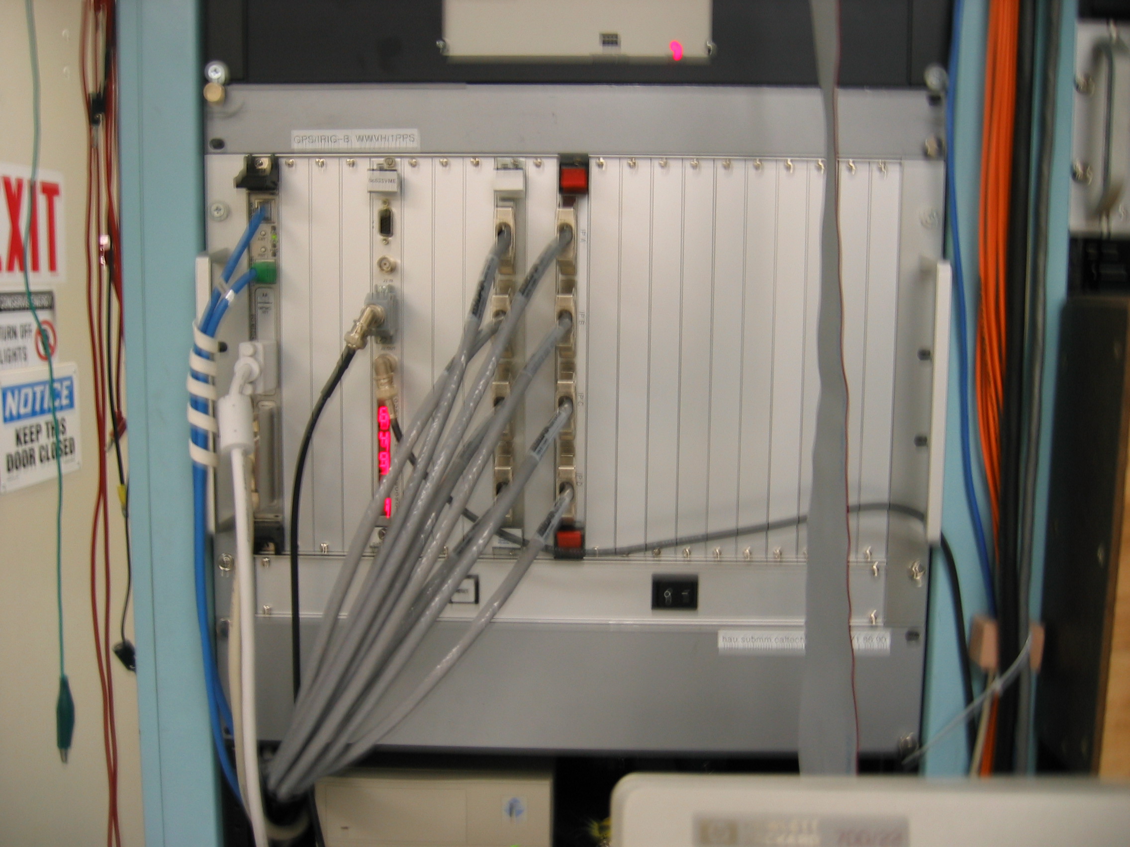
- telescope pointing timestream:
which is written to the local disk of the telescope computer (hau.submm.caltech.edu).
- rotator log, encoder log, or
housekeeping timestream:
consists not just of the dewar rotator angle but also a lot of slow
housekeeping information (observation number, object name, source
position, weather conditions, secondary status, etc. -- see the
previous section for details). The data are written locally to allegro's
hard drive.
These data streams are all eventually written to allegro's local drive by the
following programs:
- dirsync.py:
andante's local data directory, \\andante\d\das_data,
is available via Windows networking as //andante/das_data. It is
cross-mounted to allegro
as allegro:/smb/andante.
dirsync copies the
bolometer timestream data from this cross-mounted disk to the local
disk /data00. More
specifically, dirsync
synchronizes the file listings in /smb/andante/YYYYMMDD
and /data00/rawdir/YYYYMMDD,
thus ensuring that all raw data files are copied from andante to allegro. The files have
names of the form raw_YYMMDD_MMMM.bin
where MMMM is minute of
day, UT.
- header_copy.py:
the telescope computer's local pointing log directory, hau:/var/plog, is cross-mounted
to allegro as allegro:/data/plog. header_copy copies these files
from this cross-mounted disk to the local disk /data00. More
specifically, it synchronizes the file lists in /data/plog and /data00/headerdir/YYYYMMDD.
It has a look-back time of order 10 minutes -- i.e., it does not copy
all the pointing log files in hau:/var/plog,
only those from the last 10 minutes. These files are simply named
MMMM by the UT minute
of day. For this reason, the files in hau:/var/plog are overwritten
every 24 hours, so pointing log files must be copied over in
pseudo-real-time or they are lost.
- write_log:
this is the program that actually acquires the rotator position data
from the rotator encoder and the housekeeping information via RPC from
the telescope computer, described in more detail above. It writes
its output files locally to /data00/encdir/YYYYMMDD.
As indicated in the daily
startup instructions,
one starts these programs by running the shell script start_tel_util on allegro.
Merging
Merging consists of combining the three aforementioned data streams
into a single file that is then processed by the Analysis
Software. The program that does this is called merge. The source code
sits in allegro:/home/observer/src/merge.
An executable is usually copied to kilauea and run
there.
Normally, all you will need to do is follow the instruction on the Daily Observing Tasks page to
start merging by typing start_merge
YYYYMMDD. If merging crashes and you need to restart, you
can follow the instructions on the Troubleshooting
page.
Details on what merge does
It should be noted that merge
is a somewhat stupid program in that it does not attempt to time
synchronize the data. It assumes that the three timestreams are
already perfectly aligned in time and just writes them to the file as
such. A time offset between the encoder log data and the other
streams is not too important since the encoder log data stream changes
slowly and only updates once per second. On the other hand,
synchronization of the bolometer and pointing timestreams is
critical. The Analysis Software
performs this synchronization later in the analysis chain. File
boundaries can be a problem in this respect; this is why we slice the
data by observation. Slicing is described in more detail on the Analysis Software page. Slicing
just consists of putting all the time samples for a given observation
in one continuous file, so samples can only be lost at the very start
or end of the observation. Usually, there is enough slop in the
start and end of observations that no samples are truly lost.
Though, if the DAS computer becomes unsynchronized from the telescope
computer by more than a few seconds, data can be lost. This is
guarded against by expressly time-synchronizing the DAS computer to the
telescope computer as explained above.
Another important job of merge
is to convert the telescope pointing information into a more easily
interpreted form. We won't go into the details of how the
telescope pointing information is stored (see Hiro's page
for details, note that it is only accessible from caltech.edu addresses), but
suffice it to say that it is more complicated than one would
figure. merge
converts this information to current-epoch equatorial coordinates RA and dec, regardless of what form it
starts in.
merge also puts other
quantities into more usable form. The GRT analog voltage
measurement is converted to ohms. The chopper encoder monitor
voltage is converted to arcsec.
The files output by merge are
1 hour long, exactly, starting on the UT
hour. merge writes
its output files in netCDF format. netCDF is a
publicly-available, self-describing format (see their official web page
for details). When merge
creates its
output file, it creates a full size (1 hour) file filled with default
values (that are clearly invalid), and then, minute-by-minute, rewrites
the invalid data with valid data.
netCDF files contained named variables. You can use the utility ncdump (installed on allegro and kilauea, available from the
above web site) to display the header information for a netCDF file
(which lists the defined dimensions and the variables, with their sizes
and types) and to list the data for a given variable or
variables. The data is listed in its stored, not scaled and
offset form, so you will get a bunch of short int numbers for the
bolometer timestreams, for example. To look at the data in a
netCDF file, the simplest way is to use the standardly available IDL
routines, which are documented in the IDL online help. Our analysis pipeline has wrapper
routines that can make this easier.
Running merge in
standalone mode
The usage is (you can get this message by typing merge with no
arguments):
Usage:
merge -ff fileformat -cs calspecfile
-r rawdir [-h headerdir] [-e encoderdir]
[-nstart start_das_num] [-nend end_das_num]
[-fixut] [-fixnfs]
fileformat argument should be one of following:
0: December 2001 format, no LST data in encoder log files
1: December 2001 format, with LST data in encoder log files
2: May 2002 format
3: January 2003 through February 2004 format
4: May 2004 and
later format
Output files
will be
written to the current working directory.
- Recall from above that rawdir is the directory
on allegro to which the
raw data files from andante
are copied, headerdir
refers to the directory to which the telescope pointing log files are
copied from the telescope computer, and encoderdir refers to the
directory on allegro to
which the housekeeping/rotator encoder log files are written.
Pointing
log and housekeeping files are in theory optional, but it is very
difficult to use data that does not have them. Raw data files are
essential.
- -nstart and -nend
arguments indicate the first and last minutes to be merged. They
are
only needed if you want to do a partial remerging or skip over a
problem section of the data. If -nstart is not specified, merge starts with the first DAS
files it finds in rawdir.
If -nend is not
specified, merge waits
for new DAS files appear. In this mode, to stop the program, one
has to hit ctrl-c or kill
the process otherwise.
- The -fixut and -fixnfs
flags should always be turned on; these allow for fixes to minor
glitches in the data stream that arise because of either problems with
the telescope computer reading the GPS clock or problems in copying of
pointing log files over NFS from the telescope computer.
- The -ff flag should
always use the most recent format, unless you are remerging old data.
- calspecfile:
This file defines the scale factors and offsets that convert between
the variable stored in the netCDF file and its true value. For
example, bolometer AC lockin signals have scale factor 3.05e-4 and
offset 0
because they are stored in short
int form in the netCDF file and the
conversion from short int
to float voltage is by
multiplying by the
scale factor and adding the offset. However, none of this
information
is used in the way it was meant to be used, so we end up with the ADC_CAL and ADC_OFFSET in bolocam.h
also. In spite of it not being used, the code still requires that
this
file exist and all variables have an entry in it. If you add
a new
signal to the DAS, be sure to add it to CS.bolocam.fall01. As of
May, 2004, the appropriate calspecfile
to use is CS.bolocam.fall01,
which is located in /home/observer/src/merge.
Someday merge may be
rewritten so it makes sensible use of CS.bolocam.fall01.
- As indicated, you have no choice where the output files are
written.
Once started, merge runs
through the available raw data, minute-by-minute, spitting the merged
data to an output file. When it uses up all the available raw
data, and assuming the -nend
argument is not used, merge
sits and waits until the next raw data file appears. If it finds
a raw data file, but no pointing log or encoder log file (when the -h and/or -e arguments have been used),
the program will wait for a couple minutes for it to show up, and then
quit if it does not appear. This
is why you must always run start_tel_util
before beginning the DAS -- if you start the DAS first, you will end up
with raw data files that have no associated pointing log or encoder log
files.
The typical reason you would have for running merge directly (rather than
using the standard startup at the telescope) is when, after a run, you
need to go through and merge around any problem files. Typical
problems:
- If a DAS file is short or missing, you need to skip around it by
using the -nstart and -nend arguments.
- If a pointing log file is problematic (e.g., wrong day, wrong
size, missing), you can again skip around it using the -nstart and -nend arguments.
- Encoder log files can be problematic in more subtle ways.
If write_log hangs for
some reason, or dies, you could end up with a short file. Encoder
files can be completely missing if write_log hangs or dies.
The observation number in the encoder log file could be reset if write_log is restarted without
the appropriate nlast
keyword (see the Troubleshooting page). Some of these problems
can be fixed with clever use of awk.
Some are irrecoverable. Typically, dealing with a few short or
missing files here and there is not worth the effort; just merge around
them. If a large portion of a night is affected by some problem,
you might be able to correct the files and remerge. Each case is
special.
In general, if you need to merge around a hole, you should delete the
original merged file first so that you are assured the hole will be
filled with clearly invalid values.
Necessary
configuration information
Much configuration information must be supplied to merge
so that it knows what columns of the input data files corresponds to
which quantities and which netCDF variables they should be output
to.
That information is, stupidly, supplied in two different files:
- bolocam.h: The
location of bolocam.h is
specified in the Makefile
that sits in the merge
source code directory. bolocam.h
is an include file that must be present at compilation of the
executable. bolocam.h
contains a number of variable definitions:
- Assorted #define
statements define the sizes of assorted variables. We know it is
lame
that this stuff is not read from the data files themselves.
- Generic scale factors and offsets for the ADCs: ADC_CAL, ADC_OFFSET.
- Some special quantites have unusual scale factors or offsets,
so we define those here; e.g., GRT_SCALE_FACTOR,
ADC_CAL_GRT, ADC_OFFSET_GRT.
- CHAN_CODES is
the most important variable -- it defines the names of the channels
that are read in by the DAS in their DAS channel order. If you
run a new signal into a
free DAS channel, you have to modify the appropriate line of this
variable
to name it.
- AC_BOLOS, DC_BOLOS, BIAS_AC,
BIAS_DC, and MISC_DAS
define assorted groups of variables that end up lumped into a single
variable in the merged file or are processed in the same way.
- BOLO_PARAM and ARR_PARAM define new variables
that are defined for the first time in the merged file.
- CS.bolocam.fall01:
the calspecfile mentioned
above. This file needs to be present at run-time, though you can
put it anywhere you like. For example, if you copy merge from allegro to a different machine
(e.g., kilauea), put the calspecfile wherever you want
and just be sure to supply the full filename with the -cs calling parameter to merge.
Disk Cross-Mounting
and Soft Linking
Disk mounting and cross-mounting is needed for the file-copying and
merging programs
to work. You will need the root
passwords for the various machines, which are in the white Bolocam
Manual binder. Instructions:
- mounting \\andante\d\das_data
on allegro: Go to /smb. Become root. Follow the
instructions in the AAAREADME
file that is located there. Be sure that andante is properly set up to
share D:\DAS_DATA and
subdirectories thereof.
- JS 20091027 WE NO LONGER NEED TO MOUNT HAU!!, plog information is
transmitted via TCPIP.
mounting hau:/var/plog
on allegro: As root, just type mount /data/plog. If
there are any problems, either hau
is preventing allegro
from connecting (in which case, you have to contact Hiro Yoshida) or someone
has messed with the mounting setup on allegro (in which case, contact
the Bolocam support person)
- Make sure you have logged out of
the root account on allegro.
- reboot kilauea into
Red Hat 9 instead of SuSE linux.
- mount allegro:/data00
on kilauea: As root, just type mount /data00. If you
have problems, either allegro
is preventing kilauea
from connecting or kilauea
is not permitting cross-mounts from allegro. In either case,
contact the Bolocam support person.
- Merged data is usually written to the /bigdisk/bolocam/YYYYMM/merged/
directory
on kilauea (where YYYYMM is the year and month of
the current run). /bigdisk
should automatically be mounted, but it would be wise to
quickly check
that /bigdisk/bolocam/YYYYMM/merged/
exists, and create it if it does not. If /bigdisk does not exist, there
may
be a disk problem causing the disk to be unavailable. Contact Ruisheng Peng and the Bolocam support person.
If you are feeling like a linux expert, you can try to solve any
cross-mounting problems. Typical culprits are errors or incorrect
setup in /etc/fstab, /etc/exports, /etc/hosts.allow, /etc/hosts.deny, or firewall
setup that prevents connections.
You also need to make sure the following soft links are
in place (due to hard-coded filenames) in kilauea:/home/kilauea/bolocam/data:
rawdir
->
/data00/rawdir
headerdir ->
/data00/headerdir
encdir ->
/data00/encdir
merged -> your
desired merged file directory (e.g., /bigdisk/bolocam/200506/merged)
You can make soft links using the shell command ln -s target link_name where link_name is the soft link and target is what you want the
link to point to. For example, to create the rawdir soft link, you would do
ln -s /data00/rawdir
/home/kilauea/bolocam/data/rawdir
After creating the soft links, the directory listings should be as
follows (do ls -l
/home/kilauea/bolocam/data on kilauea):
lrwxrwxrwx
1 bolocam
users 14
2004-03-24 22:08 encdir -> /data00/encdir
lrwxrwxrwx 1
bolocam
users 17
2004-03-24 22:08 headerdir -> /data00/headerdir
lrwxrwxrwx 1
bolocam
users 27
2004-07-06 18:08 merged -> /bigdisk/bolocam/200506/merged/
lrwxrwxrwx 1
bolocam
users 14
2004-03-24 22:08 rawdir -> /data00/rawdir
Revision History
- 2004/01/14 SG
First version
- 2004/01/29 SG
Minor formatting changes
- 2004/01/29 SG
Add links to get back to main pages.
- 2004/02/04 SG
Add docs on merging, soft links, and cross-mounting of disks.
- 2004/04/26 SG
Add rotator section.
- 2004/04/27 SG
Clarifications and updates.
- 2004/05/02 SG
merge has been modifed so that calspecfile is not hardcoded, modify
docs to account for this
- 2004/05/03 SG
Add information on how to deal with GetEncoderStatus error messages
- 2004/05/09 SG
Add information on remote access to andante
- 2004/05/13 SG
Add lots of picture, more detail.
- 2004/05/26 SG
Switch to using mdadm for RAID.
- 2004/10/02 SG
More details on soft links.
- 2004/10/30 SG
Update RAID start and mounting instructions.
- 2004/12/10 SG
Provide link to Bolocam internal page with details on rotator motor,
encoder, and fiber optic isolators.
- 2005/02/21 SG
Update RAID instructions, add notes to log out from root account.
- 2005/02/24 SG
More updates on RAID instructions.
- 2005/03/18 SG
Update disk cross-mounting and soft links to just use /data/bolocam for
merged data -- no longer have firewire RAID, using internal SCSI
RAID. Also, no longer need to use allegro:/data/encdir, software
was modified to not have this hardcoded. Modify remote access
information to use Microsoft Remote Desktop Connection.
- 2005/06/03 SG
Modify some of the andante remote connection instructions.
Updates for the fact that /bigdisk is now on kilauea and all the
processed data goes there.
- 2005/09/11 PR
update link to DASchannel.pdf, and various sections (new rotator mounting assembly, Where To Find, RDC minor corrections), pics (allegro, fiber optics, rotator, ...)
- 2009/10/27 JS
update to show that we no longer mount hau on allegro.
Questions or
comments?
Contact the Bolocam support person.