llegr
Bolocam Web Page: Setting up for Observing
Setting up for Observing
- Summary and
Planning
- Glossary
- Orientation and
Directions
- Mirror Installation
- Rotator Installation
and Removal
- Optics Box
Installation and Removal
- Optical Alignment
- Dewar
Installation/Removal
- Moving the dewar down
to the alidade
- Mounting the dewar on
the optics box
- Cabling Setup
- Rotator Electronics
Setup and Cabling
- Telescope Interface
Cabling
- Physical Routing of
Cables
- Electronics Setup
- Revision History
Back to BolocamWebPage
Back to ExpertManual
Summary and Planning
At least in the near term, it will be necessary to mount Bolocam from
scratch on the day that observing begins -- usually another instrument
has been in use at the Cass focus up until the night before run
start. This procedure takes essentially all day, from about 9 am
to usually 6 or 7 pm. Plan your manpower accordingly. The
overall order of the steps for mounting, along with the persons who are
usually responsible, are:
- Dismount previous Cass focus instrument (day crew)
- Mount Bolocam optics box at Cass focus (day crew)
- Bring Bolocam and dewar cart down to alidade platform (day crew +
instrument team)
- Test mount Bolocam to optics box (instrument team)
- Start fridge cycle with Bolocam on cart on alidade (instrument
team)
- Align Bolocam optics (instrument team)
- Mount Bolocam and set up all cabling (instrument team)
Items 1. and 2. can be done by the day crew alone, so the instrument
team members need not even be at the summit for these steps.
Depending on which instrument was at the Cass focus prior to Bolocam,
these steps are usually done by 10 am or 11 am; consult with the day
crew on this.
Any necessary preparation of the optics box should be done prior to the
instrument switch day. This includes
- installing any mirrors that
may have been removed (should not be necessary now that SuZIE uses our
optics)
- installation of our rotator and rotator plate (only necessary
if SuZIE has used the optics box between our runs)
- touching up the
eccosorb
- taking off the right side circle panels and the front and
back side panels in order to allow access for alignment
- installation
of any panels that can be in place during optical alignment
- making
sure you've found all the plates, turnbuckles, bolts, and alignment
tools
Do everything possible before the day of the instrument
switch, as you already have plenty to do on that day!
In terms of fridge cycling, what we usually do is to hold off on the
fridge cycle until the dewar has been moved down to the alidade and a
test mount to the optics box has been done. The fridge cycle can
then occur while the optics box is being aligned and cables are
being routed over from the racks on the third floor. It is
necessary to wait until the end of the cycle to mount the dewar
onto the optics box. One could in theory do the cycle in the
morning before bringing the dewar down, but one might reduce the hold
time with all the jostling during moving of the dewar.
In terms of cryogen fills, it is best to do a LHe fill while the dewar
is still on the 3rd floor, and then do both LN and LHe after the dewar
is in its final position on the optics box. The LHe is needed for
the fridge cycle, while adding LN early will just unnecessarily
increase the weight of the dewar.
Glossary
- access panels: the
circular panels attached to the side of the optics box that allow
access to the inside of the box.
- black plate: the
black-anodized steel plate used to mount the optics box to the
telescope. It has a large circular hole in it, the same size as
the large circular hole on the optics box input-side face.
- black frame: the black
steel frame permanently attached to the telescope that the black plate
mounts to
- rotator: refers to the
cylindrical rotator assembly; there are two pieces, the piece that
mounts to the box and the piece that the dewar sits on. They are
held together by a bearing, allowing them to rotate relative to one
another.
- rotator plate: the plate
that attaches to the optics box and accepts the rotator. It has a
large circular hole in it, and some markings where the rotator
electronics mount.
- side blocks: the blocks
on the two sides of the optics box that are used to control the
position of the tilt axis of the Bolocam tertiary mirror mount
- telescope stop button or stop button or stop: large red buttons distributed
around the telescope (1st floor apron, alidade platform, control room,
4th floor near crane) that cut the power to the telescope and dome
drive. These should be pushed in when you are doing work that
requires the telescope remain stationary; you never know what the drive
motors could do!
- tertiary mirror: the
small ellipsoidal mirror that serves as an optical relay to the sidecab
instruments. It's on a flip mount so that it can be folded out of
the way for Cass focus observations. We will also refer to the
Bolocam ellipsoidal mirror in the optics box as the tertiary mirror; in
general, context will prevent confusion. The modifiers "CSO" and
"Bolocam" will be used to distinguish the two where confusion may arise.
- tertiary mirror mount:
the large flat plate that the Bolocam tertiary mirror is bolted
to. This mount has many degrees of freedom, described below.
- tertiary mirror stop:
this is a funny-shaped piece of metal that serves as a stop to fix the
position of the CSO tertiary mirror.
- tilt-axis push-pull screws:
these are the two screws at the corner of the Bolocam tertiary that
allow you
to control its rotation angle about the Bolocam tertiary mount tilt
axis.
- worm gear: the large
screw jacketed in a black bellows on the left side of the alidade
platform. It drives the elevation motion of the telescope.
Orientation and
Directions
- The front of the
optics box is the end that the light enters through; i.e., the end with
the circular hole.
- The back
is where the rotator and dewar mount.
- Right and left assume that you are standing
behind the optics box, looking toward the front of it. To be
clear, when mounted, the worm gear is on the left side of the box and
the alidade stop button is on the right side.
- Down and up are usually only used from the
point of view of someone standing behind the box, and refer to down to
the floor and up to the dish.
- Clockwise
and counterclockwise assume
that you are again standing behind the box looking down the optical
axis (time-reversed sense).
Mirror Installation
Rotator Installation
and Removal
It is up to you whether you want to install the rotator before or after
the optics box has been attached to the telescope. It tends to
unbalance the optics box weight a bit and so makes it harder to lift
down to the alidade and install, but getting it on beforehand saves
about 30 minutes so is certainly worthwhile.
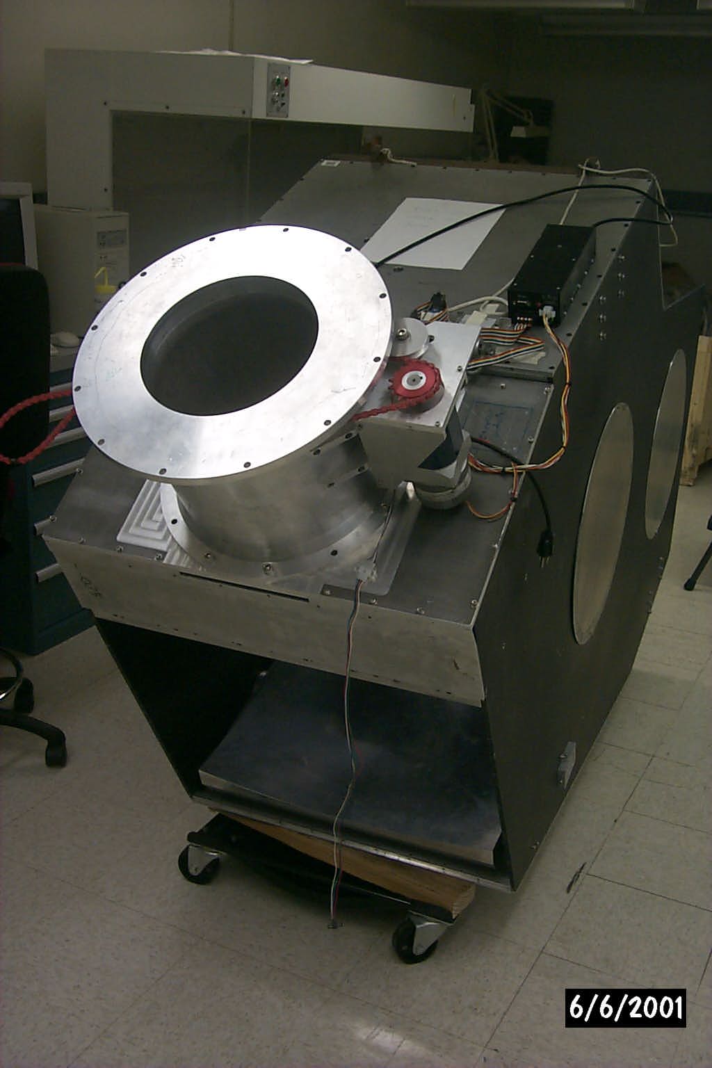
Here's a picture of the optics box
with the rotator installed.
If the homing sensor and limit switch have already been installed, be
careful to avoid damaging them!
Installing the rotator is trivial, but takes 3 people due to its
weight. You can get away with 2, but 3 makes it easier. The two
lifters can't be 90-pound weaklings. Remember, lift with your legs, not your
back! Here are the steps:
- Make sure the correct rotator
plate is in place on the optics box; the Bolocam plate is
heftier than the SuZIE plate and has a flat milled region that the
rotator mates to. There is only one way that the plate can fit on
the optics box.
- Bring the rotator behind the optics box, rotating it so the motor
mount points due right.
- Check that four surfaces are clean: the mating surface on the
rotator plate, the mating flange on the rotator, the curved flange down
inside the optics box that the bottom of the rotator will rest on, and
the bottom of the rotator. Clean any other crud off the rotator
so it doesn't end up on the optics.
- The two people doing the lifting should stand on the right and
left sides of the rotator. The third person (who doesn't need to
be particularly strong) should stand behind the rotator.
- The two lifters should grab the rotator at the top flange (the
one that mates to the dewar), lift the rotator straight up and then
over the rotator plate hole. Think ahead of time about how high
the rotator will have to be lifted and set your grip accordingly.
- The third person should push the bottom of the rotator from
behind so it tilts and goes into the rotator plate hole.
- As the rotator drops in, it usually hangs up; the third person
just needs to provide more tilt.
- Once the rotator has dropped into place, it is stable (i.e., the
lifters can let go). Rotate the mating flange so it lines up with
the large bolt holes in the rotator plate and screw it in. Again,
make sure the motor mount points due right
before you screw in.
Removal is also easy, just reverse the above steps. Screw the
rotator-rotator plate mating bolts back into the rotator plate so they
don't get lost.
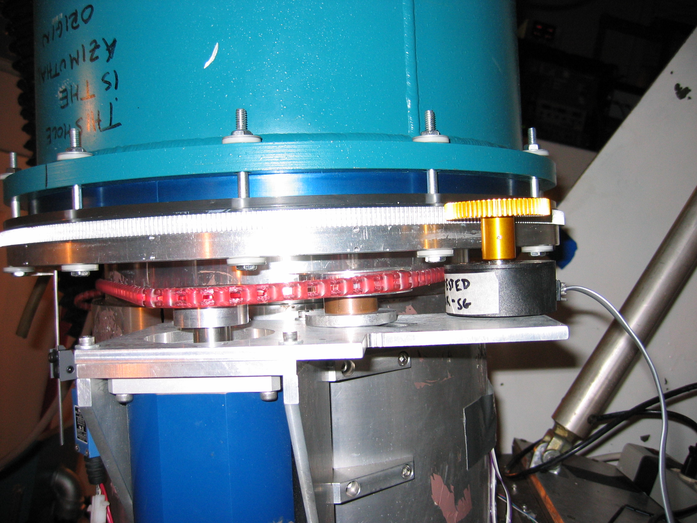
Attaching the motor and belt:
- The motor sits in an aluminum mounting frame that mates in an
obvious manner to 8 large bolt holes on the side of the rotator; see
the picture. A minor
problem is that
the threaded holes in the rotator are drilled radially while the
through holes in the motor mount are drill vertically, so it's
difficult to get some of the screws in. You should be able to get
enough screws in to ensure stability.
- On the upper end of the motor frame, next to the gear, there is a
slot for the pulley; see the picture
to see
how this should look when installed. The pulley can slide toward
and away from the rotator; it is used to take up slack in the rotator
belt. The pulley is fixed in place by tightening the shoulder
bolt that goes through the center of the pulley (there is a special nut
on the bottom of the plate that accepts the shoulder bolt). In
theory the shoulder bolt (because it has a shoulder) should allow the
pulley to freely rotate. In practice, the pulley gets a little
tight, but it's ok, the belt can slide on the pulley anyways and the
motor has enough torque to put up with the extra friction.
- The belt is attached to the rotator using two clamps. The
clamps have dowel pins sticking out their bottom sides that mate to the
belt, preventing the belt from slipping once the clamps are
installed. There is some freedom as to how to install the clamps
-- there are multiple pairs of mounting holes and the clamps can be put
on in one of two orientations. Use the maximally separated set of
mounting holes; the clamp orientation doesn't matter too much, but try
to choose it to minimize the slack in the belt. See the picture
for a view of the clamp positions and how the belt looks when
installed. Use the limit switch tab (the thing sticking downward
from the dewar mounting flange) as a reference point. Note that
you should mesh the belt with the gear during this process to get the
clamp placement right.
- Slide the pulley to take up any remaining slack in the belt.
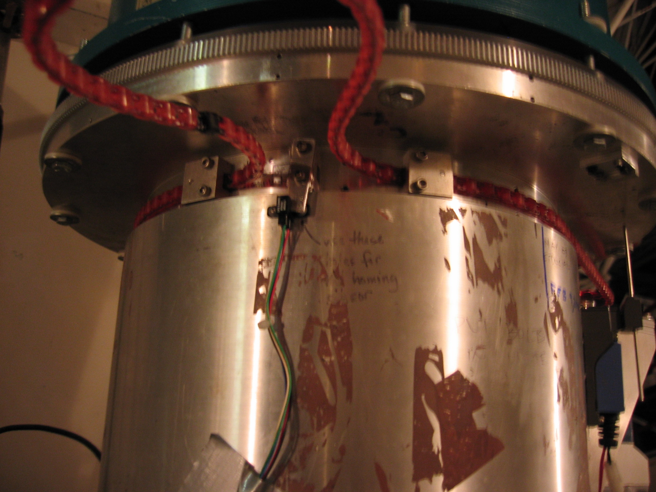
Attaching the homing tab and sensor, limit switch, and encoder:
- The homing sensor is a small IR
sensor with a slot in it that
senses when the homing tab passes through it. The sensor attaches
to the stationary part of the rotator, just below the belt.
There's some freedom in the mounting, don't worry too much about it.
- The homing tab is just a small, bent piece of sheet metal that is
attached to the rotating part of the rotator with a small clamp similar
to the belt clamps. You can see it in this picture, it is under the free loop
in the belt between the two belt clamps. You will have to tweak
so it passes cleanly through the slot in the homing sensor.
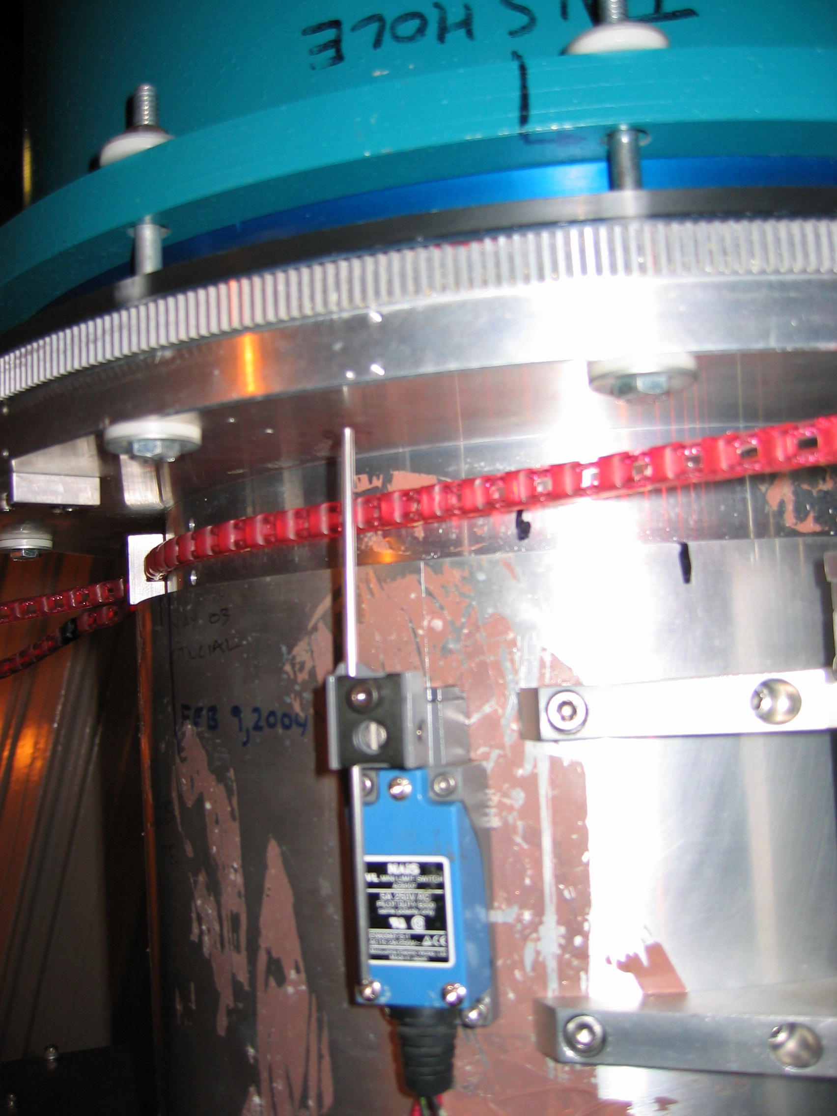
- The limit switch sits just to the
left of the motor mount.
Note that the mounting screws are different sizes and not all of them
go in! Just make sure it is stable. If necessary, adjust
the length of the switch shaft so it will be pushed by the limit switch
tab (a small aluminum right-angle tab attached to the bottom side of
the dewar mounting flange). Try rotating the rotator and making
sure the tab trips the switch but that the switch shaft otherwise does
not interfere with the motion of the rotator.
- The encoder attaches to the two slotted holes near the pulley;
see the picture. The
attachment is
obvious. The encoder should be adjusted so that the gear on its
shaft meshes well with the gear on the rotator.
Optics Box
Installation and Removal
The day crew are really the experts on this; they will drop the optics
box onto the alidade, wheel it into position, and then
lift it up and bolt it to the telescope frame at its front end. A
couple of useful bits of information or things to watch out for:
- The optics box mates to the telescope via the black plate. This plate is
attached first to the black frame
that is permanently fixed to the telescope, and then the face of the
box with the large circular hole is bolted to it. The instrument
team should check that all the parts are easily available (i.e., make
sure the you find the black plate, also dig up the screws if possible)
so that this can be done easily.
- In addition to the black plate interface, there are two
turnbuckles that attach to the optics box just ahead of the
rotator. Find these ahead of time also. The day crew will
usually install them for you, but you should check they are
tight. They will be adjusted during optical alignment.
- It is easier if you clear out any obstructions near the black
frame ahead of time, though you can usually get access after the box
has been installed. Especially, remove the CSO tertiary mirror
stop
(put the parts on the shelf on the alidade so they are easily found!)
and make sure the CSO tertiary mirror is out of the way. If you
are
multiplexing with the heterodyne receivers, make sure you know where
you have put the parts as they will need to be reinstalled for
heterodyne observing.
- Remember to remove the front panel of the optics box (nearest the
first flat mirror) before the optics box is mounted -- having the front
panel open will make it easier to do the optical alignment. It is
easier to remove before the box is mounted, but can be done
afterward. You will have to reattach the panel with the optics
box mounted by crawling back behind the box. It is doable.
Similarly, the day crew will take care of removal of the optics box
once the dewar has been dismounted and is out of the way.
Optical Alignment
The general strategy is to make use of the telescope as the reference
surface and align relative to it. You will first level the box,
then dead-reckon align the two flats, then laser align the
tertiary. Make sure the front and back plates and right side
access panels are off so you can put the level on the mirrors.
- Level the optics box
- Start with the telescope tilted to ZA = 4 degrees. This
is
usually the position that the telescope is in when the optics box is
mounted to it. Hit the telescope stop button on the alidade
platform.
- Zero out the digital level on the black frame. Be careful to
hold
the level flush to a surface so that you are sure it is perpendicular
to the ZA direction (the front-back direction); the slight ZA tilt can
cause errors in your zeroing if you are not careful.
- Level the optics box using the turnbuckles. Place the
digital level on the optics box input plate (the one mating to the
black plate), using some piece of the box to make sure the level is
perpendicular to the ZA direction. Adjust the turnbuckles until
they are tight and the box is level in the left-right direction.
They must be tight or the box will move when the dewar is attached.
- Check the front-back tilt of the box. Rotate the digital
level so it points along the front-back direction. The level
should read an angle equal to the current ZA. Record the number
for later reference.
- Align the flat mirrors:
- Release the alidade stop button, move the telescope to ZA =
26.19 degrees, and hit the stop button again. This is the angle
that the two flat mirrors will
be tilted relative to the optics box. By tilting the telescope,
all you have to do is level the mirrors, which is much easier than
setting to 26.19 degrees in one direction and leveling in the other.
- Level the flat mirrors. Set the level down on the center
of
the mirror, aligned with the direction you want to level. Each
mirror has 4 screws accessible through the optics box cover plates via
hex-head T-drivers. I think the driver needed is 9/64", though
this should be confirmed. The screws are "pull" screws -- when
tightened, they pull on the section of the mirror mount to which they
are attached. So, to change the mirror tilt along a given
direction, you have to tighten one and loosen the other of the two
screws along that axis. You should be able to level to roughly
the readout precision of the level (0.1 degrees). Check the
leveling at multiple places on the mirror; you will get 0.1 to 0.2
degree variations, but not more than that. As you are leveling,
make sure the screws are nice and tight; you don't want the mirror to
move around as the optics box tilts.
- Align the Bolocam tertiary. You have dead reckoned the
flat mirrors, so now the idea is to send a laser beam out along the
optical axis and look for its spot on the secondary, tweaking the
tertiary until the laser is centered on the secondary.
- Release the alidade stop button, tilt the telescope to ZA = 10
degrees or so, close the dome so you can see the laser, and hit the
stop button again. The slight
ZA tilt will make it easier to get at the tertiary adjustment screws,
which are accessible via holes in the bottom of the box using T-drivers.
- Install the laser jig on the rotator. By feel, you can
get the top plate of the laser jig well centered on the rotator; put in
3 bolts from the bottom side of the rotator to hold it in place.
- If the laser is not already attached and centered on the jig,
do so now. The laser sits in the V-block and is clamped by two
screw clamps. The V-block is well-centered transversely but can
slide along its long axis (there are screws to tighten it in
place). There are pre-aligned holes in the top and bottom plates
that the laser will shine through; use these to adjust the V-block so
that the beam is shining nicely through both holes. This ensures
the laser is aligned with the jig. To turn on the laser, just
screw down the endcap (it makes contact to the batteries inside and
completes the circuit).
- To determine whether the laser is aligned with the rotation
axis of the rotator, just rotate the rotator and watch the spot on the
tertiary. (Turn off the motor and/or remove the belt
to make this easy to do.) When the laser is aligned with the
rotator, the spot will not move as you rotate the rotator. If
there is misalignment, the spot will describe a circle on the tertiary
whose radius is the misalignment between the laser and the rotator
axis. (Note that the construction of the laser jig ensures that
the laser beam is at least parallel to the rotator axis to good
precision. All you have to worry about is tranverse displacement.)
- Now that you have the laser fully set up, you will adjust the
tertiary. The tertiary has multiple (too many!)
adjustments. On the sides of the optics box, you will see metal
blocks whose position is set by 4 screws (the side blocks). These blocks are
attached to the tilt axis of the tertiary mirror mount. Each
blocks can move in a plane, and the two blocks move independently, so
you have a lot of freedom to move the tertiary tilt axis. Once
these are fixed, you control the tilt of the tertiary around this
rotation axis using push pull screws at the back right corner of the
tertiary mount (the aptly named tilt-axis
push-pull screws); access to these screws is through two holes
in the bottom of the box, you will need T-drivers to get to the screws.
There is fundamentally no great way to do the adjustment. Some
degrees of freedom are degenerate, and many degrees of freedom that are
nominally independent are not really so. The process is
inevitably iterative. Some general suggestions:
- Put one person on each side of the box (one on each side
block) and one person sitting on top of the hex plate looking at the
secondary. The easiest way to get to the left side of the box is
to lie down on the alidade and pull yourself under the box to the left
side so you are sitting next to the worm gear. The right side
block person will also adjust the tilt-axis push-pull screws.
- The person looking at the secondary will be tempted to look
back down into the optics box; of course, make sure that person doesn't
end up looking down the laser beam!
- Do whatever is necessary to get the laser beam on the
secondary to start with. You have to start somewhere.
- Try to do the adjustment to get the mirror as far forward as
possible -- there have been occasions where we get the laser
satisfactorily aligned and then realize the mirror is so far back that
one cannot put the back panel on the box.
- Start with the left-right adjustment by getting the tilt of
the tilt axis correct. That is, the tilt axis ought to be
perpendicular to the sides of the box so that, when you work the
tilt-axis push pull screws, the beam only moves along the elevation
direction on the secondary. You don't want tilting of the
tertiary to cause the spot to move diagonally or transversely across
the secondary, it will cause you great misery later.
- There are always degeneracies. Even when you've got the
tilt axis squared up, there is probably a degeneracy between moving the
tilt axis and the mirror tilt angle. There's nothing you can do
about it. If the optical axis hits the wrong spot on the
tertiary, it can be for the most part corrected with the secondary
focus parameter.
- Don't get too worried about whether you are hitting the right
spot on the tertiary (if you even know where that spot is!). We
in fact demonstrated to ourselves that it is physically impossible to
hit the design spot on the tertiary and not have the mirror stick out
the back of the box. Someday we will figure out what is going on,
it's not your problem.
- Once you are happy with the alignment, tighten down all
screws. Be careful to avoid damage to any of the screws by
overtightening, or warping of the mirror mount.
- Do a check on the variation of the alignment with telescope
elevation. The person watching the spot on the secondary should
harness himself into the telescope backstructure (there are usually
harnesses in the lockers on the first floor of the dome) and ride the
telescope as one goes from ZA = 10 to ZA = 60 and back again, watching
the position of the spot as the ZA changes. There will always be
some motion, but you want it to be a small fraction of the size of the
secondary. We don't have a hard and fast spec on this, you mainly
want to make sure everything is nice and tight and there is no extreme
motion of the beam because something that should be tightened down is
not.
- Finally, remove the laser jig from the rotator, remove the
batteries from the laser and tape them to the jig, and put the jig away
in the 3rd floor lab where the rest of the Bolocam equipment is
stored. Store the digital level with the laser alignment
jig. It's very important to not lose the level or the jigs, they
are unique and trying to do the alignment with kludgey replacements is
very difficult!
Dewar
Installation/Removal
This is the part that usually inspires fear -- getting the dewar down
to the alidade platform and onto the optics box. There are two
steps: getting the dewar down to the alidade and situated on its cart
there, and then mounting the dewar on the optics box.
Moving the dewar down
to the alidade
You will remove the dewar from its cart with the crane, leave it
suspended on the crane while you move the cart down to the alidade, and
then drop the dewar down to the alidade and reattach it to its
cart. If you have trouble remembering how to deal with the
dewar straps and buckles, refer to the Messing with the Innards page.
- Put the window cap on the dewar
-- you do not want to accidentally puncture the window during any of
the following steps!
- If you have not already, do a LHe fill. Do not do a LN fill
unless you did not do one the day before.
- Remove the electronics box. This will of course require
turning off the power and disconnecting all cabling. See the Electronics page for instructions on doing
this.
- Screw the dewar eyebolts into the 4 threaded holes on the top of
the dewar (the same holes that accept the support legs). These
eyebolts are usually stored with the dewar screws.
- Wheel the dewar over to where one can access it with the
crane. The day crew will rig the dewar to the crane using the
eyebolts. Slowly take up the weight of the dewar with the
crane. When you are confident the rigging is solid, release the
dewar straps so that the dewar comes free of the dewar holder and
cart.
Leave the dewar hanging from the crane (lower it down close to the
floor so it doesn't have far to fall if something happens!).
- Disassemble the cart. Check that the cotter pin that
prevents rotation of the dewar holder is in place. The dewar
holder is attached to the cart with two aluminum rods on the back held
in place with cotter pins; you will have to remove these rods to free
the dewar holder. You have to take the weight off the rods to get
them out, but the holder is very heavy. Lower it down to a height
where one person can get a good grip on it (lifting with the legs, not
the back!) and then one other person can pull the cotter pins and
rods. Once the dewar holder is off, pull the cart legs out.
They are held in by
spring-loaded pins. Sometimes you have to tilt the cart back a
bit to get the weight off the legs. Finally, remove the crank
(also held in place by a spring-loaded pin).
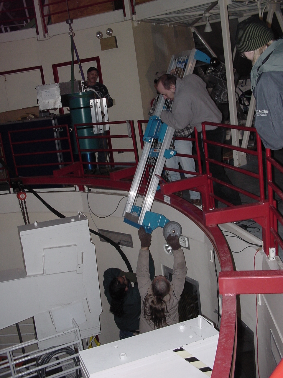
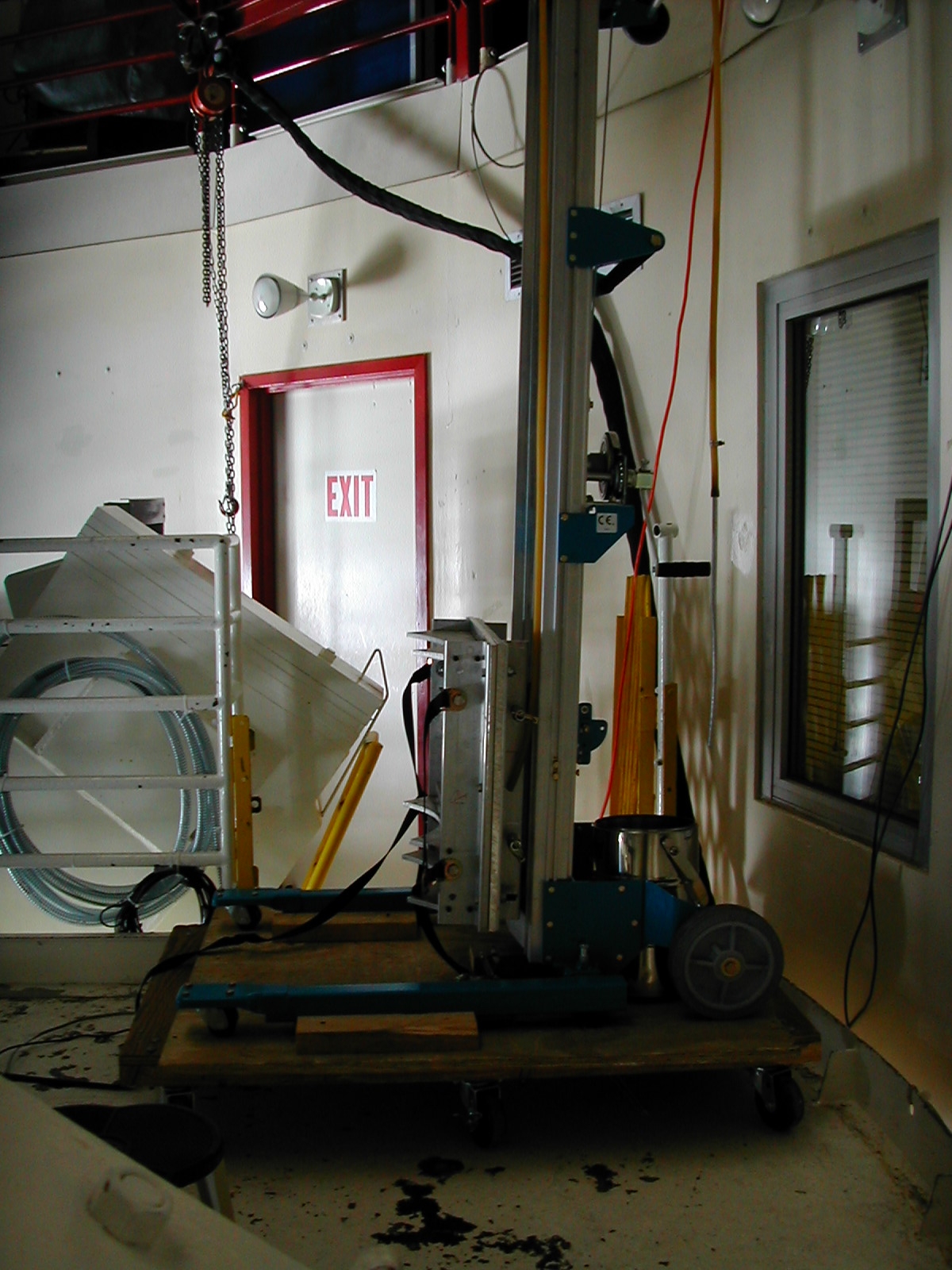
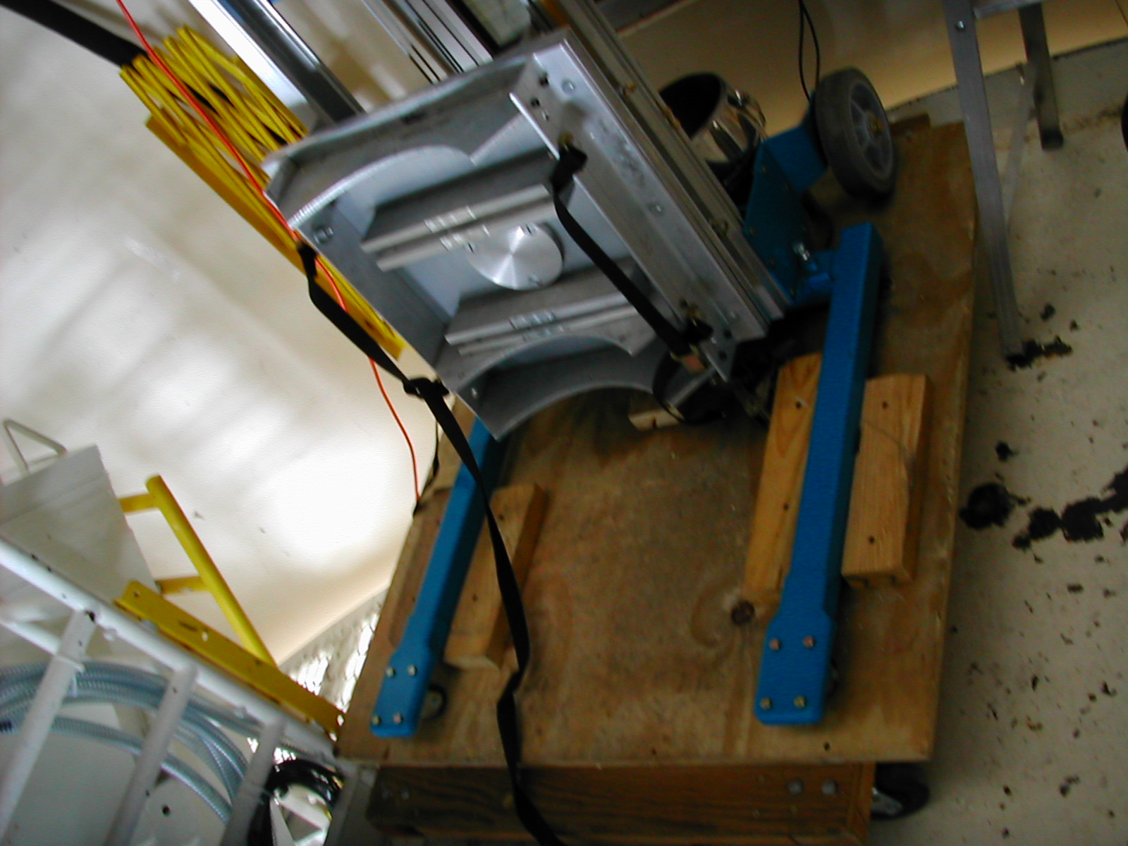
- Take the pieces down to the alidade. The cart is the
hardest part; we usually drop it down over the side directly to the
alidade, see the picture.
Remember, it's heavy and wants to catch on the red rail.
- Reassemble the cart on a large rectangular dolly on the alidade
so that it can be used to lift the dewar onto the optics box.
The orientation of the dewar on the cart is important, so we provide
some pictures of the mounting of the dewar onto the optics box to give
you a better idea: picture
1, picture 2, picture 3. As you
can see, the cart must be oriented a certain way to tilt the dewar so
that is can be mounted on the rotator, but this orientation is
incompatible with moving the cart toward the optics box as the dewar is
eased into place because it is transverse to the normal direction of
motion of the car. Hence the dolly -- it allows the cart to move
as needed. Note the orientation of the dolly on the alidade
platform, the orientation of the dewar cart on the dolly, and how the
cart must be placed to align the dewar with the rotator. See the picture
to see what your end result should be.
We usually use one of the dollies that are used for storing instruments
up on the third floor. Orient the dolly on the alidade so that
its long axis is transverse to the platform (going left-right).
Put the cart on the dolly and attach the legs. Position the cart
on the dolly so that when the dolly is pushed toward the optics box,
the dewar cart will hold the dewar in a position such that it can be
aligned with the rotator. And of course make sure the cart is
placed so that the dolly won't tip when the dewar is placed on
it! Clamp the cart into place using 2x4's screwed into the dolly;
see picture 1 and picture
2. It's hard to see in the picture but there are 2x4's along
both the legs and the along the main section of the cart; the cart is
completely immobilized.
Finally, reattach the dewar holder to the cart. This is a bit
difficult because of its weight. Again, use one person to carry
the weight of the holder and 1 or 2 others to get the aluminum rods in
and insert the cotter pins. Make sure the holder is oriented as
indicated in the picture.
- Bring the dewar down and reattach to the cart. The travel
of the crane prevents you from bringing the dewar down into the most
convenient place; the dewar usually ends up on the right half of the
alidade, so you have to rotate the dewar cart around to mate to
it. See picture 1 and
picture 2 to get an idea
of where the dewar sits when the crane lowers it to the alidade, though
note that 1) we no longer leave the e-box and dewar holder attached to
the dewar when moving it; and 2) depending on the length of your dolly,
you may have to rotate it 90 degrees to bring the cart close enough to
the dewar. Once you have the dewar close enough to the cart, you
can strap it into the dewar holder in the usual manner. Remember
to get the orientation of the dewar holder correct and to use the
correct slot in the holder to grab the dewar's middle flange; see the picture. Make sure to get the
azimuthal rotation angle of the dewar correct; the bath exhaust ports
should point back toward the cart. If you do not get close
enough, you will not be able to tilt the dewar properly for the fridge
cycle.
- If you want to do a test fit to the optics box (e.g., to make
sure you have mounted the cart onto the dolly correctly), you can do so
now; basically, just follow the directions below for attaching the
dewar to the optics box, except you don't need to bother with the
spacer and you can quit once you get close enough that it is clear the
dewar will mate properly.
- Reattach the e-box, recable it, and power up; see the Electronics page for instructions on doing
this. In routing the cables, think about how the cart will have
to be oriented during the mounting process and route the cables so they
will not interfere. This usually means they should go toward the
back of the alidade.
- At this point, you should tilt the dewar and start the fridge
cycle, and then start doing the optical alignment.
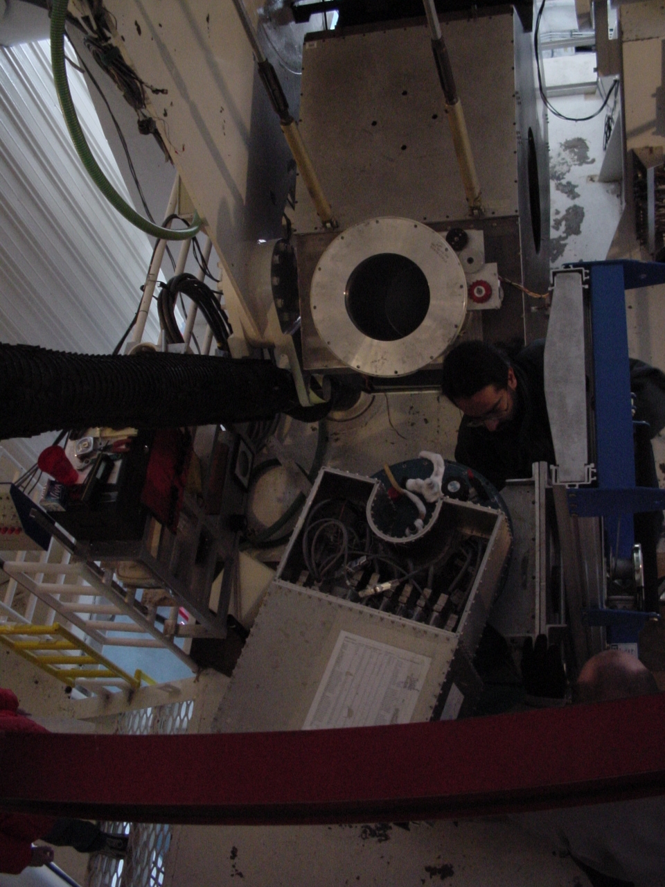
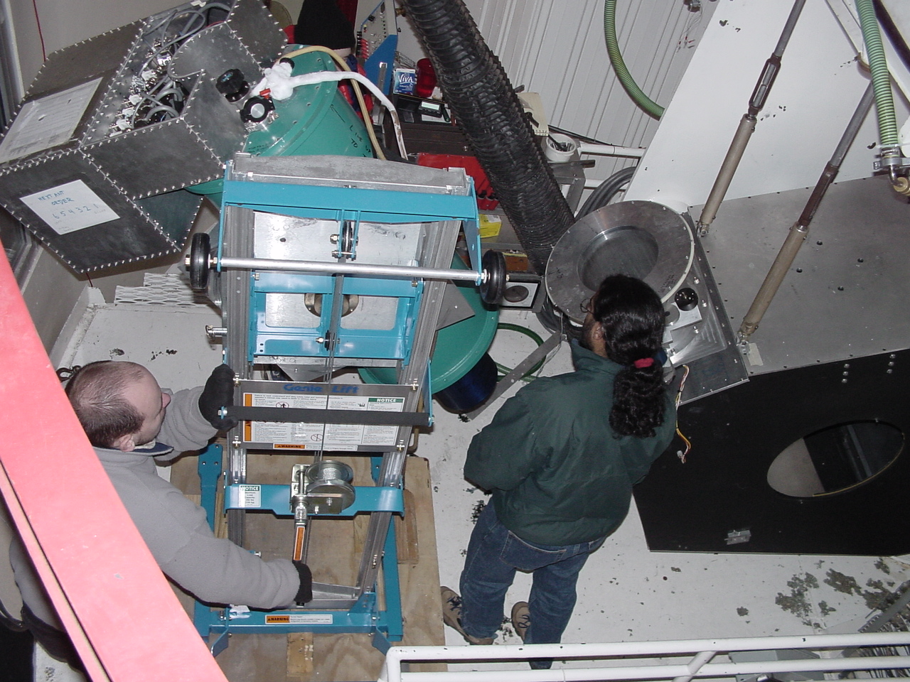
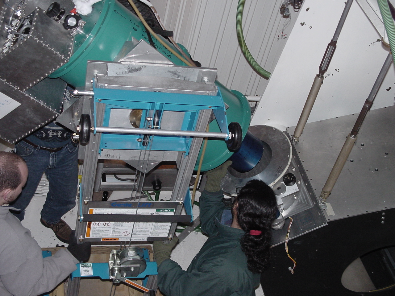
Mounting the dewar on
the optics box
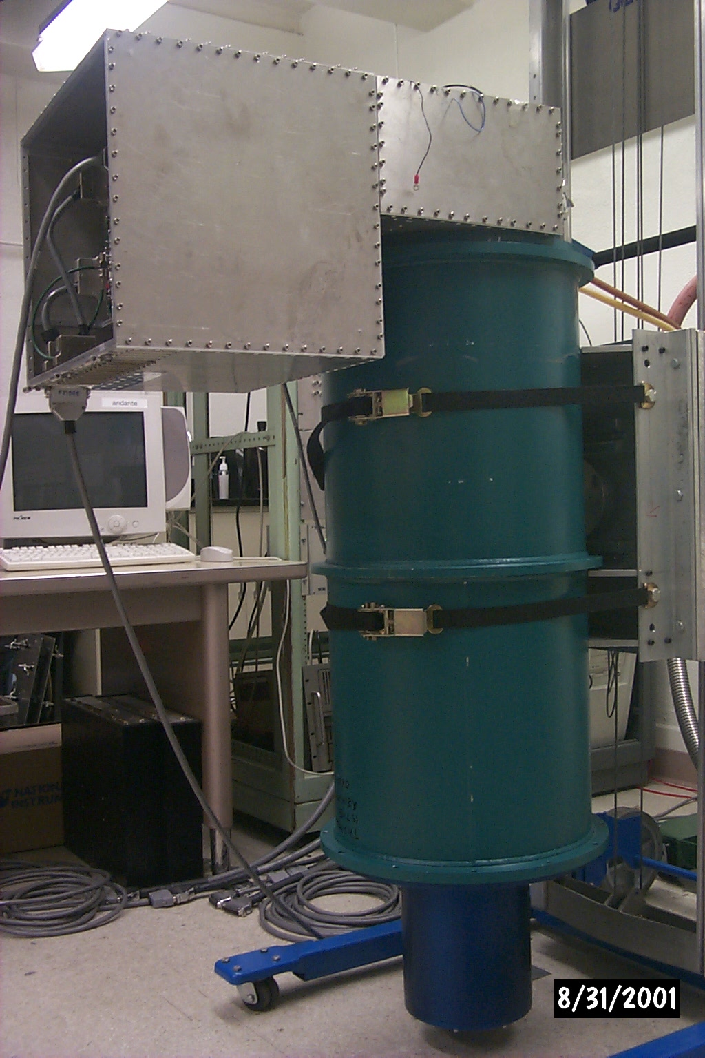
This is really not that hard. You just have to make sure you get
the orientation right. Look at these pictures to get an idea of
how it will look: picture
1, picture
2, picture
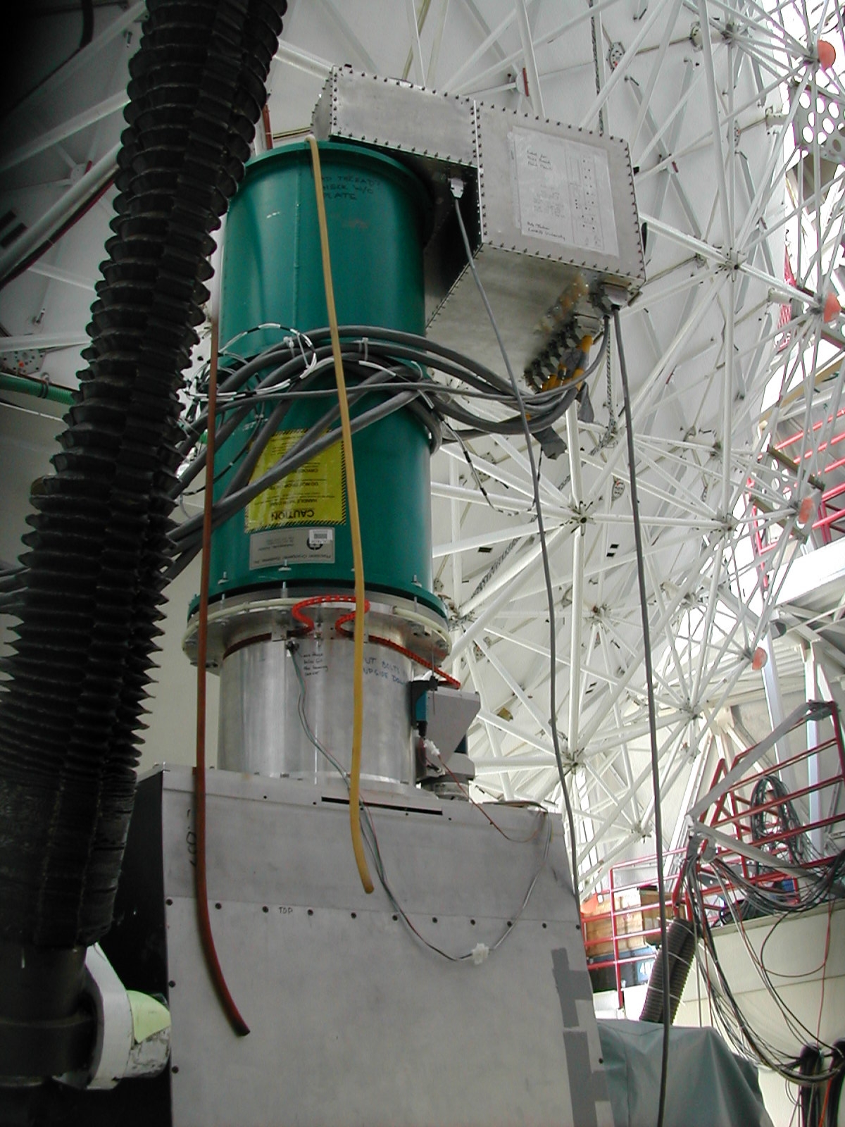
3. See also how the dewar looks when finally mounted.
Remember that you have to wait until the fridge cycle is done because
the dewar must be rotated such that it is not tilted to the fridge
cycle position.
Preparations:
- You will need 0.75 inches of lucite electrical isolated/spacer
between the dewar and the rotator. This usually
means the specialized 0.25 inch spacer (which has shoulders to clear
the rotator encoder gear) and a simple 0.5 inch spacer. These
should be in the 3rd floor Bolocam storage room.
- You will also need the special dewar mounting bolts. These
are special long bolts with hex heads and, most importantly, nylon
shoulder washers and oversized metal washers. They should be in a
tupperware container with the laser alignment jig and the digital
level. The nylon washers are important for ensuring electrical
isolation between the dewar and the optics box, and the shoulder
washers prevent the bolt heads from biting into the nylon. Make
sure you understand how they all fit together: each bolt gets two nylon
and two oversized washers, with the shafts of the nylon washers
pointing toward each other and the oversized metal washers sitting on
the large flat part of the nylon washers.
- You will also need some freedom to rotate the rotator. If
the belt is not attached, then you are all set. If it is
attached, make sure the motor is off.
- Tilt the telescope to ZA = 4 degrees and hit the alidade stop
button.
- Make sure the dewar window cap
is on!
Mounting:
- Rotate the dewar so that it is in the correct orientation for
mounting. Rather than the bath exhaust lines pointing at the
cart,
they should point 90 degrees away, counterclockwise as viewed from the
top. See the mounting picture
for clarification. To do this, you have to loosen the dewar
straps 1-2 clicks and then rotate the dewar, taking up some of the
weight yourself to reduce the friction. Loosening the straps is
tricky: you have to release the buckle and let the strap slip 1-2
notches on the ratchet and then lock again. If you loosen too much, the dewar will fall
out of the cart! The bottom strap is noncritical right now
(the top strap is the one holding the dewar to the cart), so you can
use the bottom strap for practice. You should have two spotters:
one pushing up on the e-box (who will push the dewar back toward the
cart if you loosen too much) and one at the back of the cart (to
prevent if from sliding away when the other spotter pushes). Once
you have the straps loosened, the e-box spotter and the strap-loosener
can push up on the dewar (to take the weight off the straps) and rotate
it. Once the dewar has been rotated, retighten the straps.
- Rotate the dewar rotator into the correct position. There
is a label on the rotator that says something like "E-box points this
way". If you cannot find the label, the e-box should be between
90 and 120 degrees counterclockwise (as viewed from the top) away from
the rotator belt length takeup loop. See the picture. Rotate the rotator so
the e-box label points straight down; as indicated in the mounting picture, the e-box
itself will be pointing straight down when it is mounted onto the
optics box.
- Rotate the dewar cart around so that the e-box points toward the
back of the alidade, as in the mounting picture. Make sure
any cables are moved so they will not interfere with mounting.
- Remove the dewar holder cotter pin so you will be able to rotate
the dewar.
- Get your lucite spacers in place on top of the rotator. You
may need to use some tape to hold them in place until the snout is
inserted into the rotator barrel and can catch them.
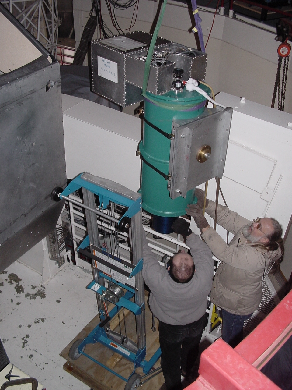
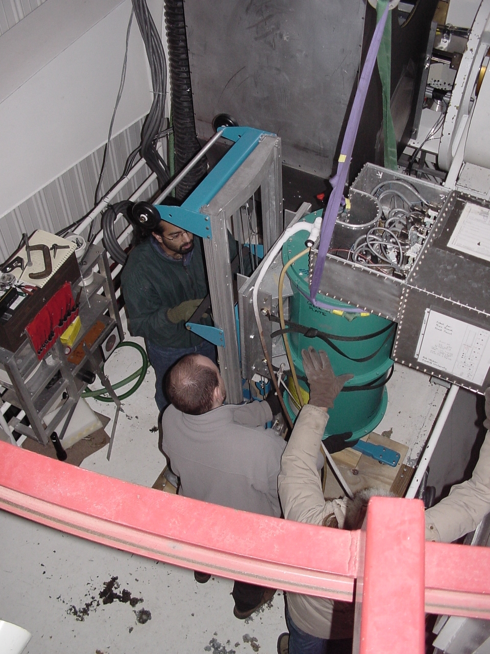
- Now you will raise the dewar up, tilt it, and slowly ease the
dewar into place by alternately pushing toward the optics box, tilting
the dewar, and lowering the dewar until it can mate to the rotator.
When raising the dewar, note that the dewar cart actually lets you go
higher than you might think; the holder will run into the top of the
cart, and you will feel resistance from the crank, but if you keep
cranking, a second mast starts moving and the dewar will go
higher. Of course, don't go so high that the entire cart becomes
unstable.
Another problem you will run into is the worm gear -- in principle, one
would like to tilt the dewar 40 degrees (the angle that the rotator is
tilted to) raise it up so that the window is above the rotator, push it
toward the optics box, and then drop it in. The dewar will
probably run into the worm gear and prevent you from doing this.
So what you must do is tilt more than 40 degrees, push the dewar toward
the optics box to get the snout into the rotator a bit, lower the dewar
a bit, tilt back toward 40 degrees a bit, push toward the optics box a
bit, and so on until the snout is feeding into the rotator. The picture shows what
things look like midway through this process.
Trust me, it can be done! You just have to keep pushing, tilting,
lowering, etc., etc.
- Once you have the dewar snout very close to touching the lucite
spacers, get all your screw holes aligned. It is useful to stick
a bolt through the holes in the rotator and spacers and then into the
dewar flange. You may need ot rotate the rotator a little bit to
get the alignment.
- Continue to ease the dewar in so that its weight comes to rest on
the rotator. Get some bolts in, starting from the top side of the
rotator (toward the telescope). Remember,
you must insert the bolts from the bottom so the shafts do not stick
out and interfere with the rotator belt, and you must use the nylon
spacers and oversized washers! See the picture. It is dangerous to
stand
under the dewar at this point, so stick to the top side bolts for
now. You will find that you have to get a couple bolts in, ease
the dewar in a bit more, tighten up the bolts a little bit, ease the
dewar in more, etc. until the dewar surface is flush against the lucite
spacer.
- Continue to add bolts. You won't be able to get a few bolts
near the rotator motor right now, but do as many of the others as you
can. Tighten them up, taking care to adjust the dewar cart height
to make this easy.
- Once you are happy with the tightness of the bolts and the
stability of the dewar, start loosening the dewar straps to release the
dewar from the holder. Start with the bottom one, and then the
top one. Be careful to watch out for any signs that the bolts are
not taking up the weight of the dewar. Once the dewar is
completely free from the cart, pull the cart away.
- Rotate the dewar counterclockwise to get access to the bolts you
missed and install them. Tighten up all the bolts. Make
sure you are happy with the stability of the dewar.
- Tilt the telescope to ZA = 4 degrees and measure the optics box
tilt angle in both left-right and front-back directions by placing the
digital level on the plate with the large circular hole. The
left-right tilt should be 0 degrees and the front-back tilt should be 4
degrees. Compare the front-back tilt to that measured earlier
after tightening the turnbuckles and leveling the optics box without
the dewar attached.
Cabling Setup
This section discusses 3 items: cabling of the rotator, cabling of the
telescope interface, and physical routing of all cables.
Rotator Electronics
Setup and Cabling
You should have already attached the motor, belt, adjusted the pulley,
and installed the homing sensor and tab, limit switch, and encoder; see
Rotator
Installation for instructions. You will now attach all the
electronics for driving the rotator, measuring its position, and
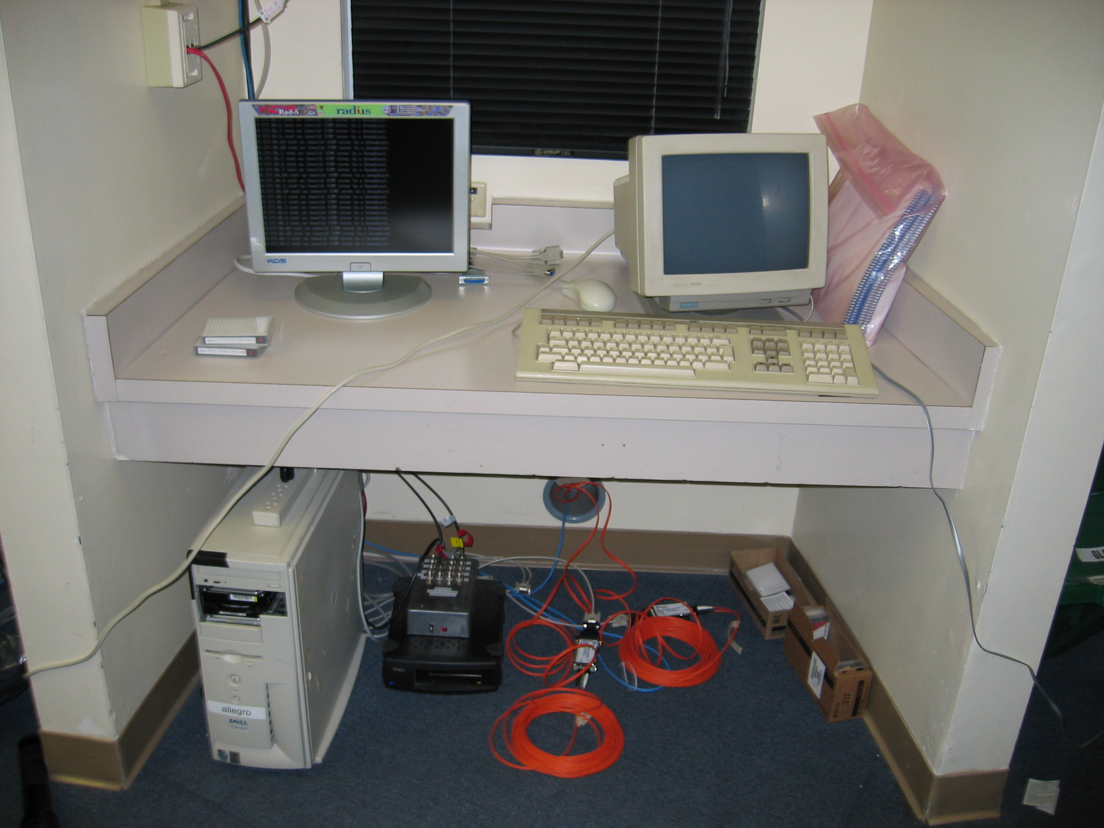
communicating with allegro. If not
already mounted to the optics
box, all the parts mentioned below should
have been found in an obvious storage place, either in the 3rd floor
Bolocam storage room or near allegro.
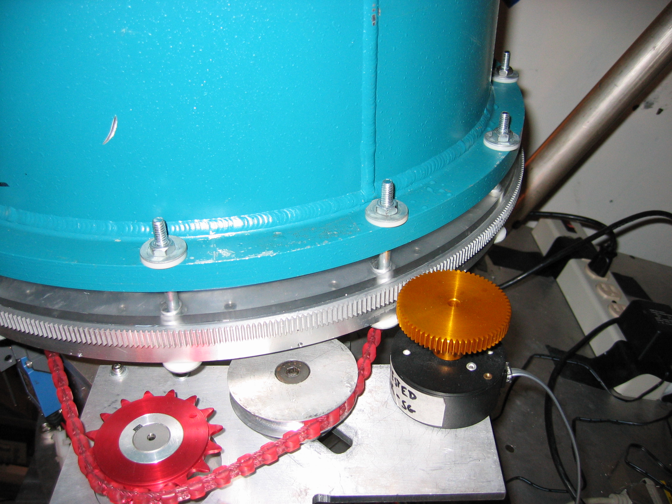
Refer to these two pictures
(double-click to get larger versions):
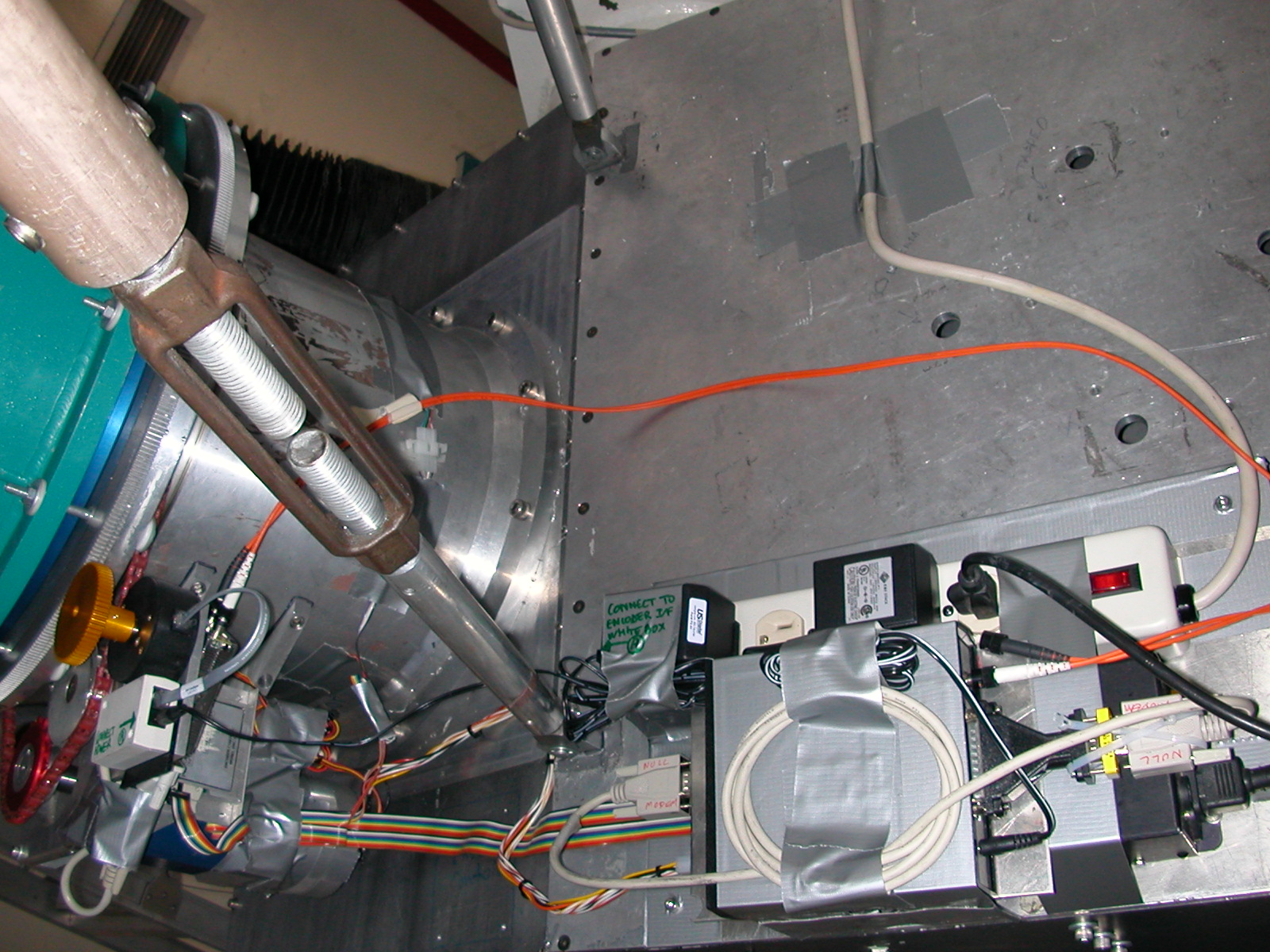
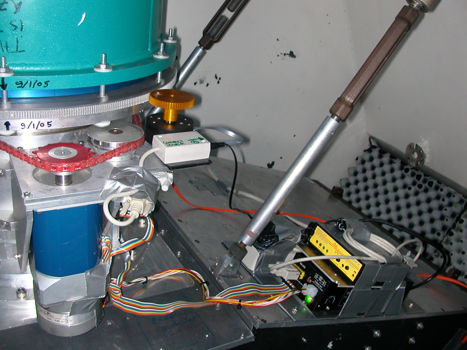
- On the optics box
- The rotator assembly consists in:
- the rotator motor and its power supply (SID 2.0 rectangular black box)
- the motor encoder and its controller (a squarish flat thing)
- the rotator encoder (gold gear) and its encoder (white small box)
- Limit switch, and home sensor
- The assembly is simplified by regrouping the hardware in two different blocks:
- A. Attached to the motor structure are the motor and its encoder, as well as the rotator encoder + adapter
- B. Mounted on an aluminum plate are the motor power supply, the motor encoder controller and a set of AC power outlets
- Mounting instructions (DO NOT TURN ON THE POWER BEFORE HAVING CABLED UP EVERYTHING - ESPECIALLY THE MOTOR TO ITS POWER SUPPLY):
- if not already done, mount the rotator onto the optic box. Already attached and cabled up should be the hardware defined above in block A. Screw in the aluminum plate defined above as block B (there are 4x 10-24 tapped hole marked in the optic box for this purpose).
- Connect the motor to its power supply (the motor has one cable with a white plastic connector; this is
the motor power cable and connects to an obviously matching connector
on the motor power supply)
- Connect the large ribbon cable to the motor power supply. This ribbon cable is made up of all wires on the rotator side going to a single connector plug on the motor power supply side. Again, the plug is keyed and unique, so not mistake possible.
- connect the DC power adapter connector to the rotator encoder controller (white box, featuring a phone cable)
- connect the AC power outlets to one of the dirty power outlet tapped down on the left side of the alidade platform that moves with the telescope.
- turn on the main power and the motor power supply.
- More Wiring details if needed:
- Apart from the motor power cable, the motor should have one more free cable; this is for the
motor shaft encoder. It should have a brown 4 or 6-pin Molex
connector that connects to one side of the motor encoder
controller. Note that the connector is keyed.
- The largest connector on the other end of
the ribbon cable that plugs into the motor power supply connects to the motor encoder controller. The
two remaining free wires connect to the homing sensor and limit switch;
they are keyed so there is no ambiguity.
- The encoder has its own additional wiring. There should
be a small white or beige assembly that has a telephone connector, a
DB9 RS232 connector, and a DC power adapter connector; this is called
the encoder adapter. The
encoder connects to this assembly via a special phone cord (should be
stored with the encoder). There should be a DC power adapter to
power this assembly; it should be plugged into dirty power as the motor
supply was.
- From the optics box to the computer. The motor power supply
and the encoder adapter each have DB9 RS232 ports for connecting to
allegro.
- The preferred method for connection uses optoisolators to avoid
connecting allegro to the
optics box.
- Connecting the encoder:
- Assignment, setup and cabling of the fiber-optic
isolators. These are just
directions for which isolator goes at which end and how to cable them,
wait for specific instructions below on when to connect them.
- You should find 2 Telebyte 271 fiber-optic-to-RS232
adapters, as well as some RS232 DB9-to-DB25 adapters. Do not
confuse the Telebyte 271 adapters with the Telebyte 274 fiber-optic
modems used
for the motor below. The Telebyte 271 modules simply convert the
RS232 port transmit and receive lines to fiber.
They require no outside power (they draw power from the RS232 port
connector). The fiber
adapter comes
in two flavors, which are labelled rotator and computer. Details and
settings:
- rotator end: adapter has red writing, a male
DB25 connector. The DCE/DTE switch should be set to DTE
(mnemonic: "TE" for "terminal end")
- computer
end:
adapter has blue writing, a female DB25 connector. The DCE/DTE
switch should be set to DCE (mnemonic: "CE" for "computer end")
- Each fiber adapter has two ports, labeled T and R
(transmit and receive) and also labeled B and W (for black and
white). You
should have found a spool of fiber-optic cable lying around. This
spool has two cables that each have 2 fibers, one cable each for the
motor power supply and the encoder adapter. They are labeled motor and encoder For the encoder cable, the connectors are
connected to the Telebyte 271 fiber adapters using the B and
W color code. (A given fiber has the same color connector on
both ends.) The connection scheme should be:
- rotator
end: T --> black, R--> white
- computer
end: T --> white, R--> black
- These adapters connect to their respective DB9
RS232 cables at the computer or rotator end using DB9-to-DB25
adapters. You will have to select the correct sex DB9-to-DB25
adapters at each end.
- Instructions for installing:
- Connect the rotator-end
Telebyte 271 (make sure you have the right one!) to the encoder DB9 RS232 cable and to the
rotator end of the encoder
fiber-optic cables. Remember, two fiber connections matching the
color code above.
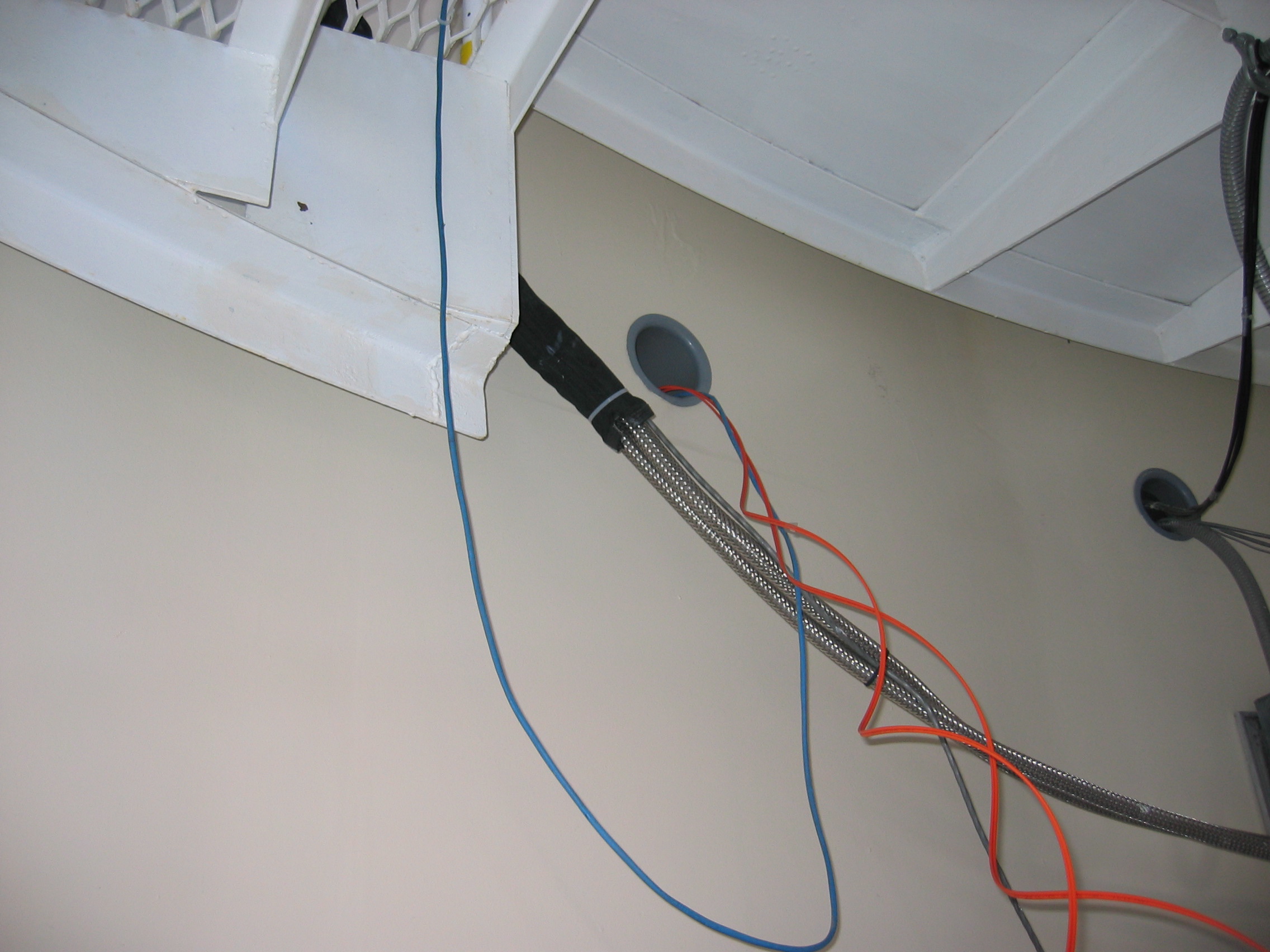
- Run the fiber-optic cables into the control
room.
The best way to do this is to run them forward along the optics box to
the
elevation bearing, down to the alidade, under the alidade, and then
back up to the hole in the control room wall near allegro. The
allowed bend radius for the fiber is 15 cm, so be careful not to bend
or cable-tie it too tightly.
- allegro
has a multi-port RS232 card. If not
already in place, you should find a cable that has a high-density D
connector
on one end and 5 standard DB9 connectors on the other end. If it
is
not already connected to allegro,
do so now (there is only one
connector port on the back of allegro
it can mate to). Of the DB9
connectors, one is labeled motor
and one encoder. Connect
the computer side Telebyte 271
to the encoder DB9
connector, using the necessary DB9-to-DB25 adapter. Connect the computer side Telebyte 271 to the encoder fiber-optic cable, again
being sure to follow the connector color scheme. Be sure to
avoid mixing up the motor and encoder
cables and to attach the fibers using the black/white color code
correctly.
- Summary for encoder
connections:
Encoder --> phone cable
--> encoder adapter (DB9F)
--> DB9M/DB25F adapter
--> Telebyte 271 labeled rotator
(DB25M)
--> two fibers labeled encoder,
rotator side (fibers: T --> B, R --> W)
--> Telebyte 271 labeled computer
(fibers: W --> T, B --> R) (DB25F)
--> DB25M/DB9F adapter
--> computer RS232 port cable labeled P1 encoder
- Connecting the motor:
- Assignment, setup and cabling of the fiber-optic
isolators. These are just
directions for which isolator modem goes at which end and how to cable
them,
wait for specific instructions below on when to connect them.
- You should find 2 Telebyte 274 fiber-optic modems,
with RS232
ports. There should also be some leftover RS232 DB9-to-DB25
adapters. Do not
confuse the Telebyte 274 modems with the Telebyte 271 adapters used for
the encoder above. (The motor needs the Telebyte 274 modems,
which are more sophisticated than the Telebyte 271 adapters, because
the motor requires hardware flow control.) The Telebyte 274
modules multiplex all the RS232 port signals onto a single
fiber-optic. The Telebyte 274 modules have their own power
supplies (including AC/DC converters) -- make sure you have found them (but leave the Telebyte 274's powered off
until everything is connected). Make sure both Telebyte
274's have their "local loopback" and
"remote loopback" switches OFF. The Telebyte 274 modules
at the two ends are identical, but have their DIP switches set
differently, so make sure you note the rotator and computer labeling. DIP switch
settings (1 = ON, 0 = OFF):
- rotator end:
switch #
|
1
|
2
|
3
|
4
|
5
|
6
|
7 |
8
|
9
|
10
|
11
|
12
|
setting
|
1
|
0
|
0
|
0
|
0
|
0
|
0
|
1
|
0
|
1
|
1
|
0
|
- computer
end:
switch #
|
1
|
2
|
3
|
4
|
5
|
6
|
7
|
8
|
9
|
10
|
11
|
12
|
setting
|
1
|
0
|
0
|
0
|
1
|
1
|
1
|
1
|
0
|
1
|
1
|
0
|
- Each Telebyte 274 has a single fiber port.
The spool of fiber that you found above has a second cable labeled motor with two fiber lines in
it. You only need one of the
lines for the motor because the Telebyte 274 modules multiplex
all the RS232 port signals onto a single fiber. You will pick one
of the fiber lines (black or white) and connect it at both ends,
leaving the other fiber line unused.
.
- Again, the Telebyte 274 modules connect to their
respective DB9 RS232 cables at the computer or rotator end using
DB9-to-DB25
adapters. You will have to select the correct sex DB9-to-DB25
adapters at each end. The
rotator-end motor RS232 cable requires a null modem adapter between the
Telebyte 274 and the motor controller. The null modem is
DB9F on both ends and pinned out as follows:
Telebyte 274
|
1/6
|
2
|
3
|
4
|
5
|
7
|
8
|
motor
|
4
|
3
|
2
|
1/6
|
5
|
8
|
7
|
Pin 9 on both ends are NC.
- Instructions for installing:
- Connect the rotator-end
Telebyte 274 (make sure you have the right one!) to the motor DB9 RS232 cable as
instructed above (including the null
modem adapter) and to the
rotator end of the motor
fiber-optic cable. Remember, you only need one fiber connection,
the other will be left dangling.
- You presumably have already run the fiber-optic
cables into the control
room.
- You presumably have already connected the
multi-port RS232 cable to allegro.
Connect
the computer side Telebyte 274
to the motor DB9
connector, using the necessary DB9-to-DB25 adapter (no null-modem
adapter needed at this end). Connect the computer side Telebyte 274 to the motor fiber-optic cable, using the
same color connector as was used at the rotator end. This will
leave one of the fiber optic lines unused. Be sure to use the
same color connector!
- When you have connected both ends, power on both
Telebyte 274 modules. You should see the DCD and Link lights come on almost
immediately. The TD and RD (transmit and receive) lights
will remain off until you issue a command to the rotator. If you
do not have DCD and Link lights, there may be a problem with the fiber,
power adapters, or DIP switch settings. Check everything, try
substituting a different fiber-optic line (you can disconnect and
temporarily use one of the encoder fiber-optic lines, for
example). If you don't get DCD and Link lights, you simply will
not be able to communicate with the motor.
- Summary for motor
connections:
Black motor controller --> gender changer DB9 M/M
--> null modem
DB9 F/F
--> gender changer DB9 M/M
--> DB9F/DB25M adapter
-->
Telebyte 274 labeled rotator
(DB25F)
--> fiber optic labeled motor,
rotator side white connector
--> fiber optic labeled motor,
computer side white connector
--> Telebyte 274 (DB25F)
--> DB25M/DB9F adapter
--> computer
RS232 port cable labeled P0 motor
- If you don't want to use the optoisolators, things are simpler.
- For the motor, there is a long black RS232 cable (DB9 on
both ends). This can be connected directly from the DB9 on the
motor power supply to the motor RS232 port cable at allegro.
- For the encoder, you should bring the encoder adapter inside
the control room and connect it directly to the encoder RS232 port
cable from allegro.
The DC power supply will of course also come
inside. The telephone cable from the encoder adapter to the
encoder should be long enough to go out from the control room to the
dewar.
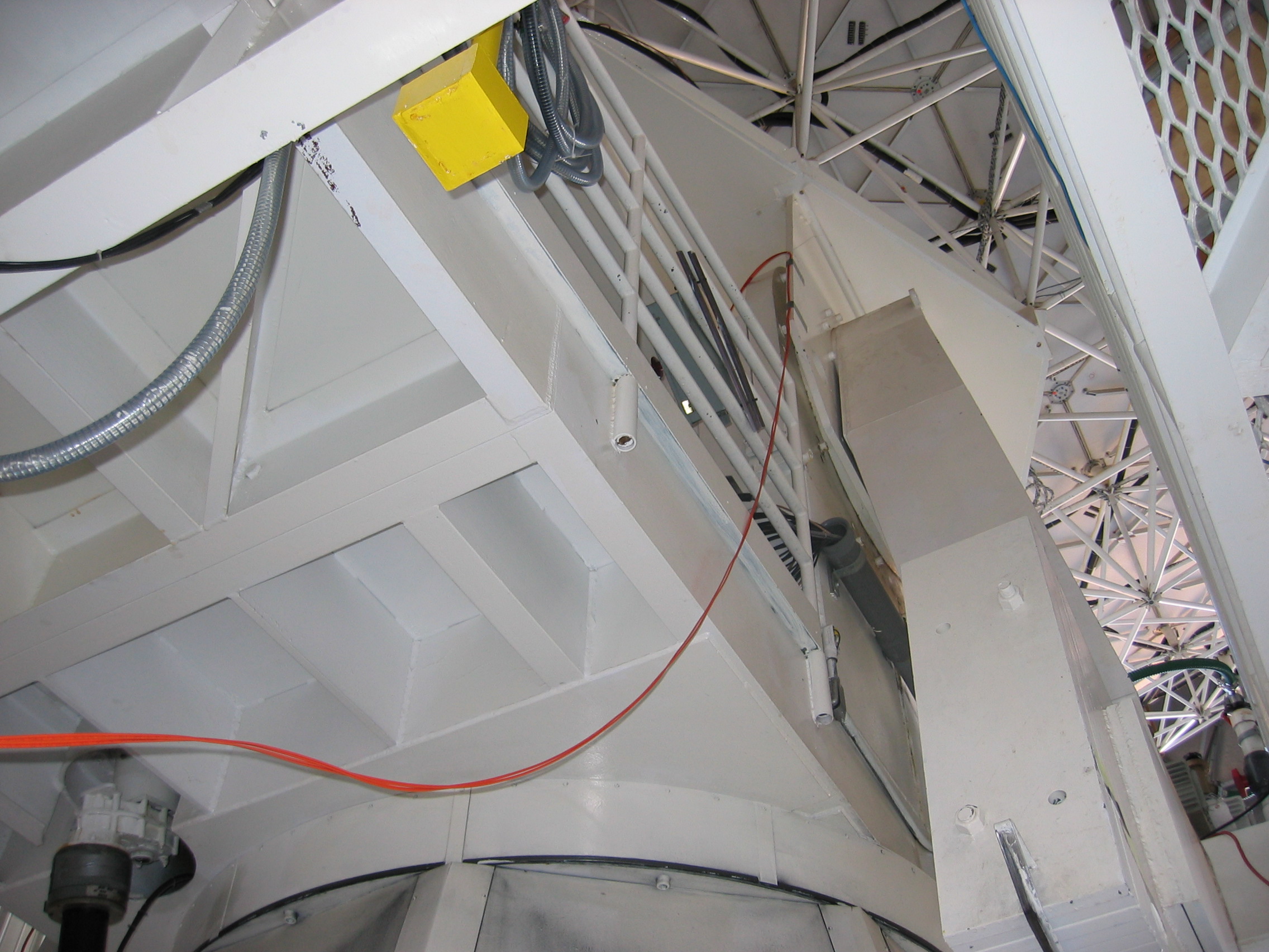
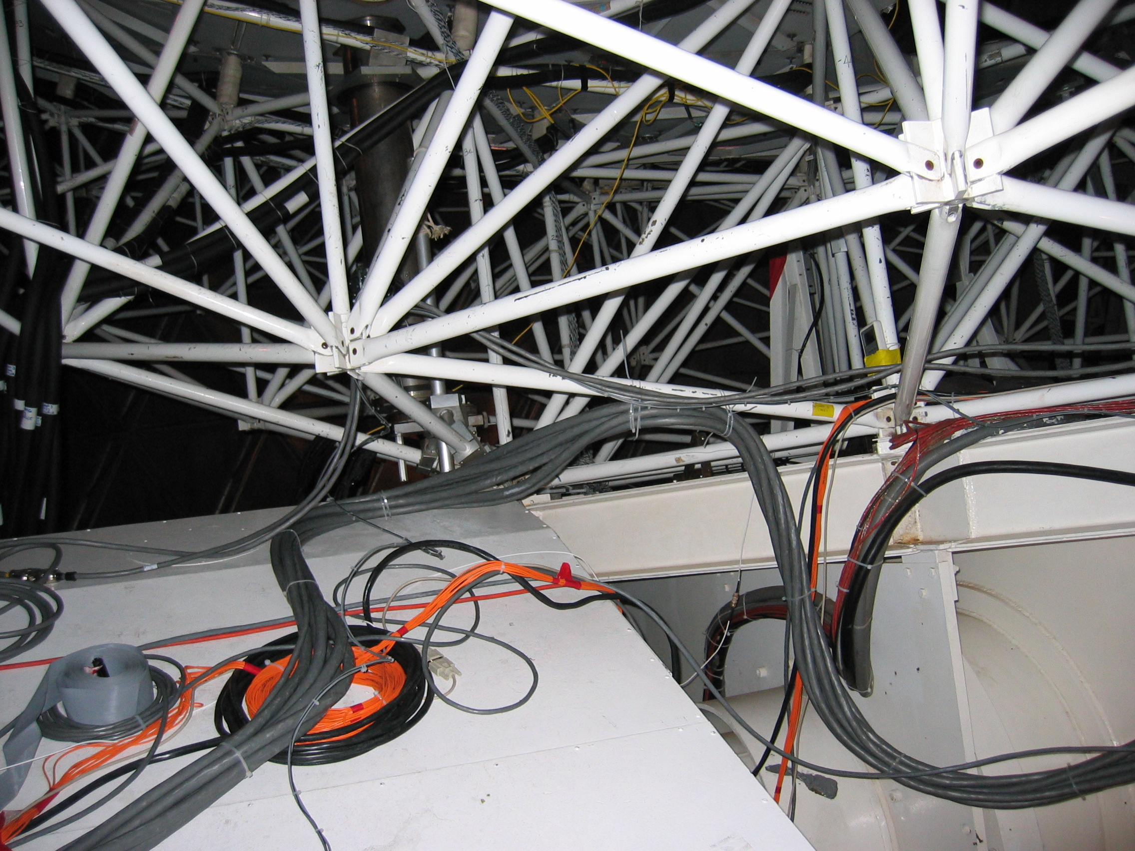
- Regardless of how you have done the cabling between allegro and
the optics box, tape or tie down all loose cables. Be careful
that you have routed the cables such that they are out of the way and
will not be damaged by telescope motion. This is shown here, here, and here; the fibers come through the
hole in the wall near allegro,
drop down below the alidade, and then
come up the elevation plate and loop over to the optics box.
- END OF RUN: You do not
need to disassemble everything you have just assembled. You will
of course have to disconnect and bundle up the fiber optic. But
you may leave all items on the optics box there, and similarly in the
computer room. But, double-bag
the rotator encoder and put a tarp over the optics box to protect these
pieces of electronics from the weather. The rotator encoder is
especially sensitive to any kind of water damage. Each one costs
$300, we do not want to have to replace it every run.
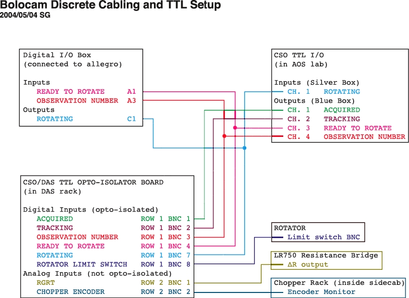
Telescope Interface
Cabling
There are multiple BNC cables that connect between the telescope
computer, allegro, and
the DAS. A schematic of the cable
connections is provided here.
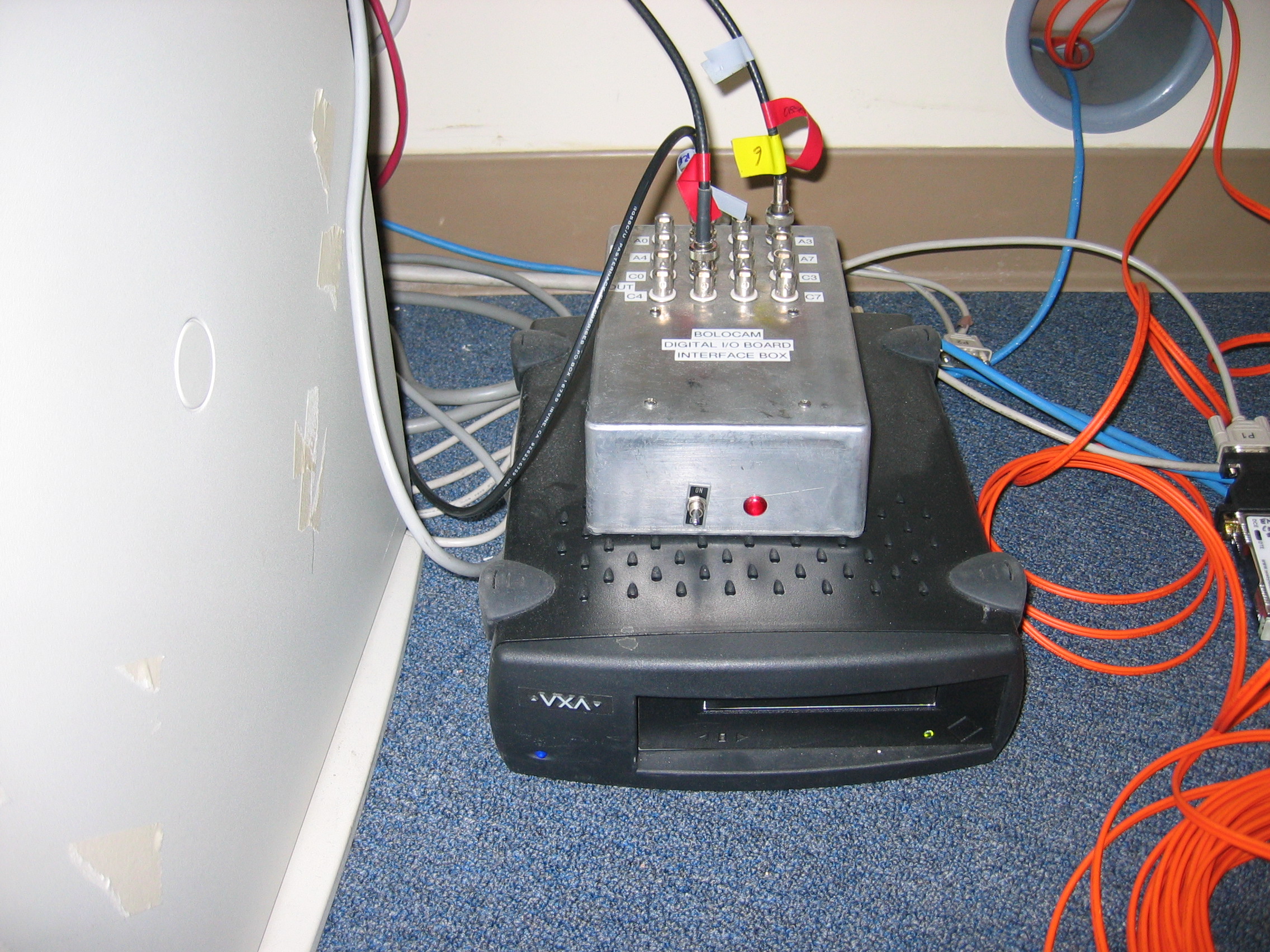
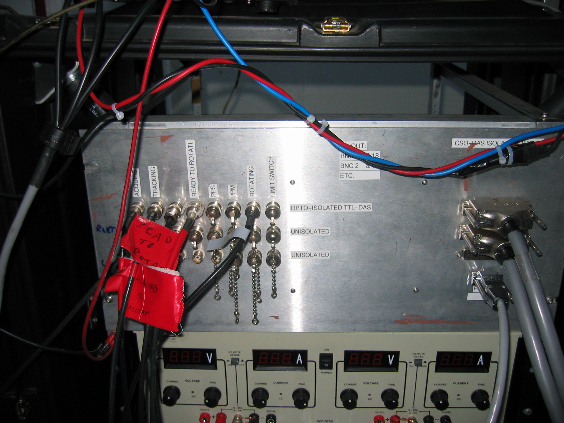
Some explanation is necessary:
- The Digital I/O on Allegro
refers to a small metal box with 16 BNC connectors that provides
isolated digital inputs and outputs for allegro.
- The Blue
Box and Silver Box
refer to boxes in the AOS
lab that the telescope computer uses for digital outputs (blue) and
inputs (silver). They are at the far right end of the wall of
racks.
- The DAS TTL Input Board
is the optoisolator board in the DAS rack referred to on the Electronics page.
- The Chopper Encoder Monitor comes
from the analog output of the secondary chopper encoder, runs out
through a hole in the sidecab (in the upper left above the
chopper-tuning oscilloscope) and up to the 3rd floor. The chopper
encoder signal MUST be
digitized in order to analyze chopped data! See the Electronics
page for where it should
connect to.
The meaning of the signals is not important now; see the discussion on
the Data Acquisition,
Rotator Control, Data Handling page for details.
These BNC cables should already be in place and connected at the
telescope computer and allegro.
They will be labeled by their
signal names at each end. If any are missing, you will have to
run new ones. If they are in place and not connected, go ahead
and connect them to the channels at each point as the diagram
indicates. The connections at the DAS rack are given on the Electronics page.
The digital I/O box at allegro
connects to allegro via a
simple
DB37/DB37 cable to a unique port on the back of allegro. Make
sure the digital I/O box power switch is on (it draws power from
allegro).
The best way to test the connections is simple to do fake observation
and see if everything works. If you find possible problems, you
can tee in DMMs on the various BNCs at the digital I/O box and also
monitor the signals going to the DAS via the DAS. All the signals
are TTL logic levels; logic 0 is between 0V and 0.5V and logic 1 is
around 3V I think.
If you find deeper problems (the signals are not being asserted by the
telescope or the digital I/O box as they should, the signals make it to
the DAS rack but the optoisolator board fails to transmit them to the
multiplexer), you will probably have to call an expert. If you
are feeling brave, schematics of the digital I/O box and the
optoisolator board can found in the Bolocam big black binder or on the Bolocam internal
web page.
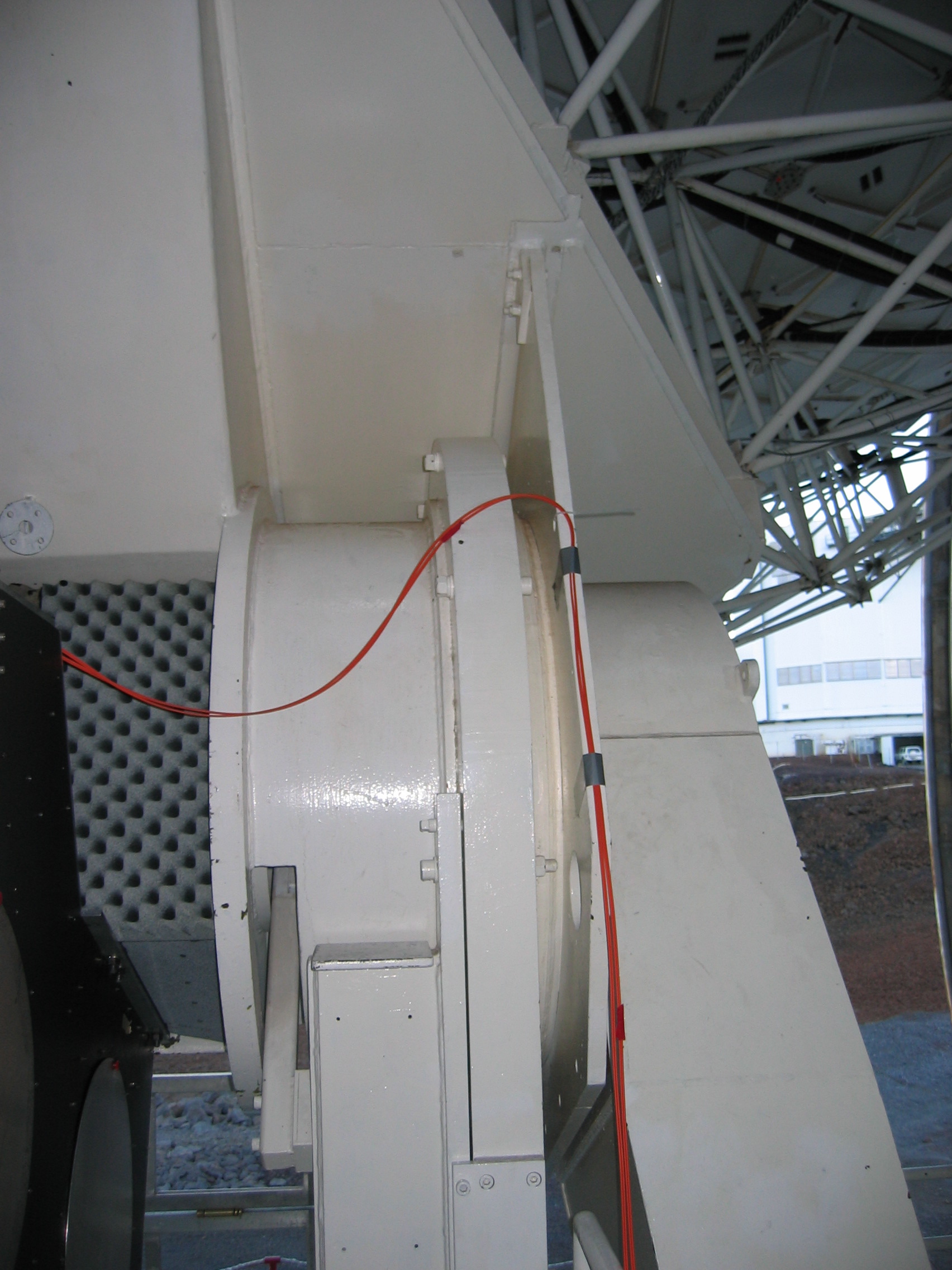
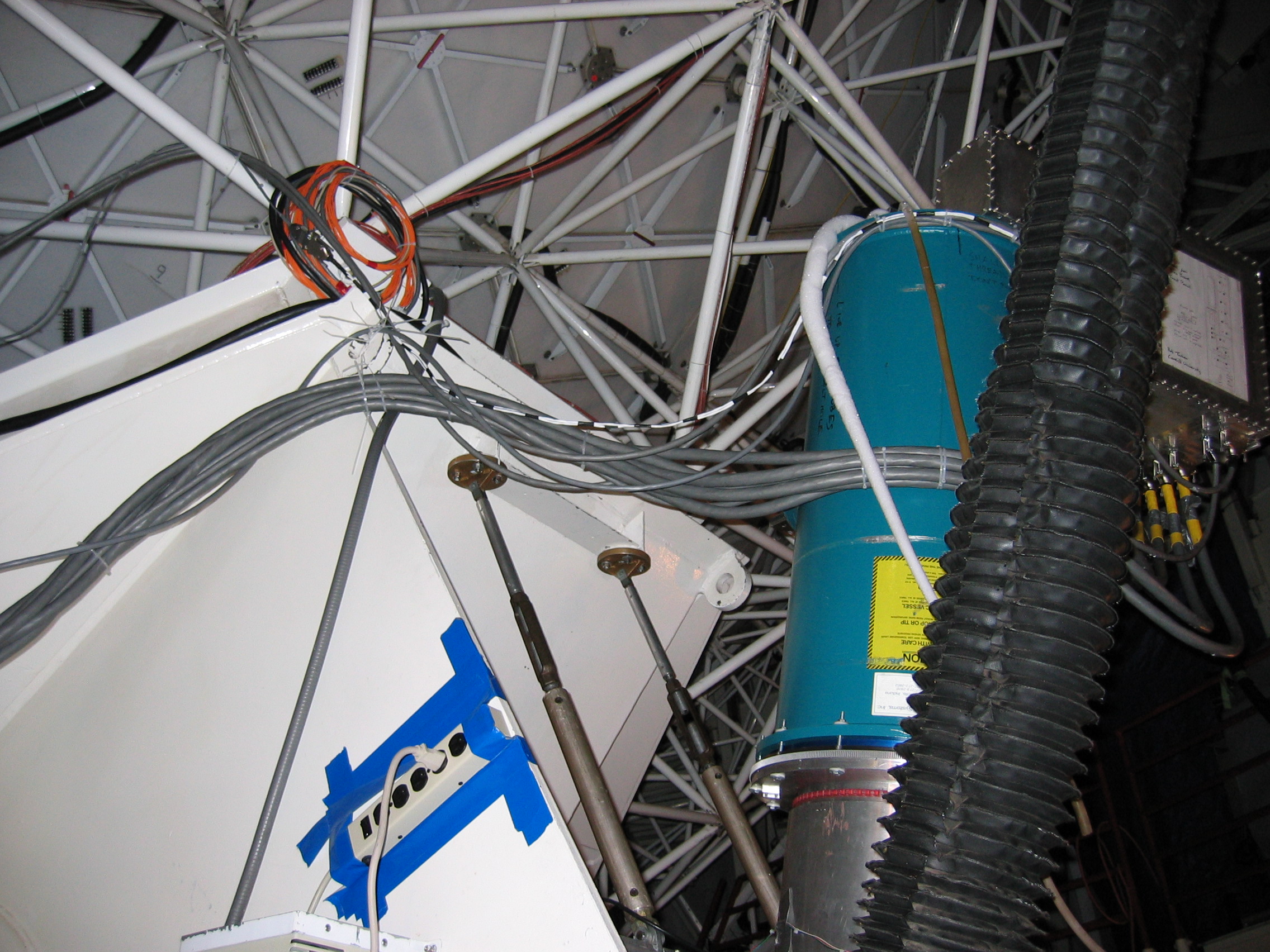
Physical Routing of
Cables
All these cables have to be run around in ways that keep them out of
the way and allow dewar and telescope motion.
The most painful to deal with are all the cables that go between the
e-box and the lockin/DAS and fridge racks. This consists of the
e-box power cable, the fridge and aux thermometry cables, the GRT
readout cable, the bias spider cable, and the 6 monster
preamp-to-lockin cables. The usual way we do this is to route the
cables from the dewar up to the hex plate, over to the elevation
bearing by the side cab, on top of the side cab, and to the
racks. It is simplest if you first route the bundle consisting of
the 6 monster cables and the bias spider. Cable ties should be
used to tie these cables to the various eyeholes along the way.
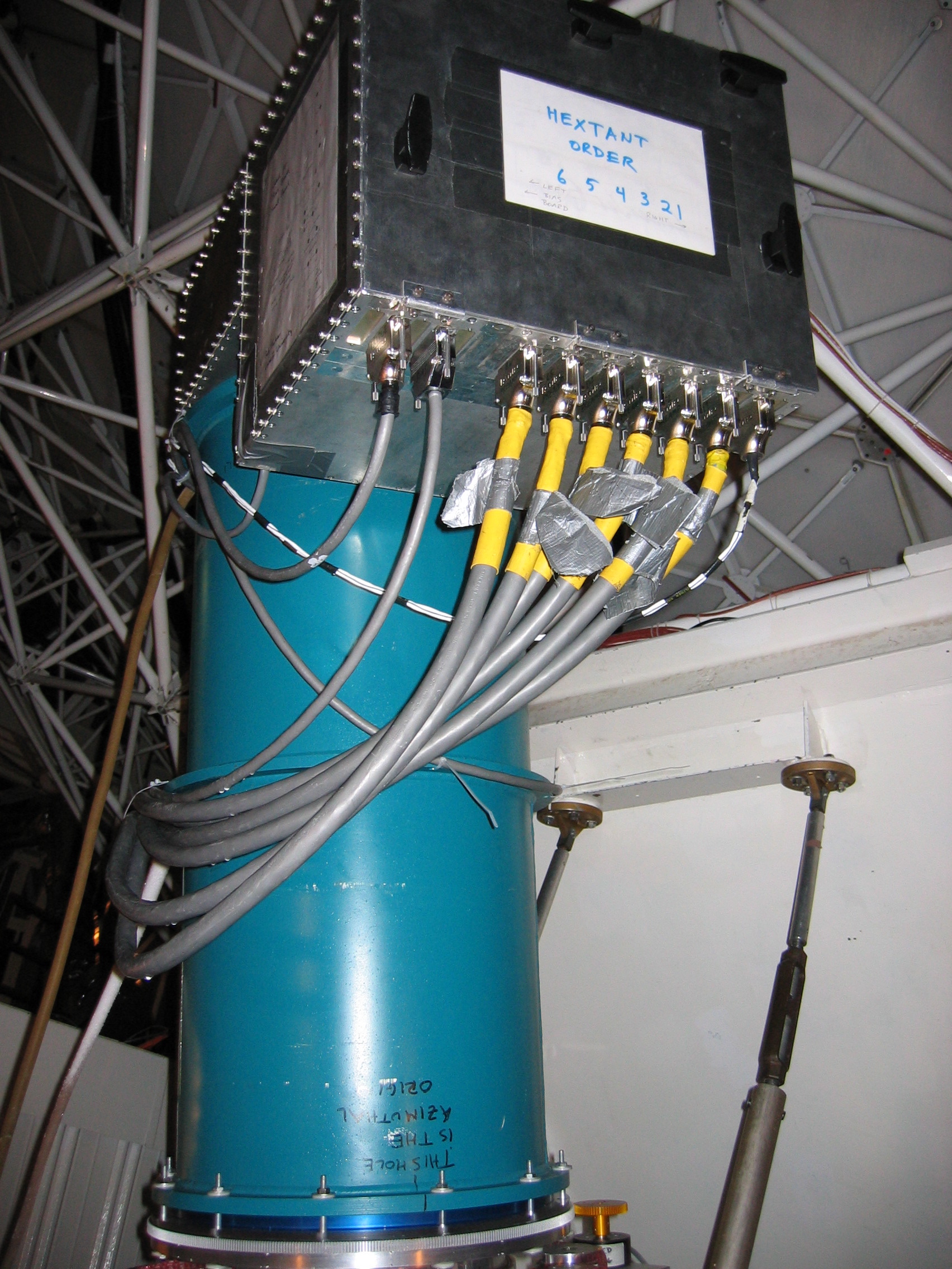
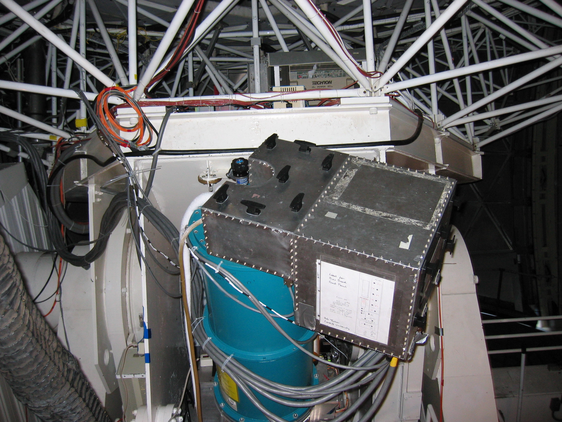
At the dewar, the cables should be cable-tied to the through holes in
the middle flange so that their weight is not resting on their
connectors to the e-box. Enough slack between the hex plate and
the dewar must be provided to allow rotation of the dewar. Some
pictures serve to illustrate:
- Views of the cabling at the dewar: from left,
from right, from back.
- View of the cables going
up
to the
hex plate.
- View of the cables coming
onto the sidecab.
Take up the slack in the monster cables on top of the side cab.
Once these guys have been run, you can run the GRT cable, the e-box
power cable, and the fridge and aux thermometry cables on top of them.
The BNC cables carrying the TTL signals are routed primarily on cable
trays. The cables come out from the blue and silver boxes in the
AOS rack and run to the cable tray above the rack. The cables
going to allegro will
branch off into a different tray running to the
control room, staying in cable trays until they drop down to the floor
near allegro. The
cables going up to the DAS run through a hole
in the AOS lab wall (the same hole used for cables going to the
sidecab) and then run up between the AOS lab wall and the sidecab up to
the 3rd floor.
As mentioned above, the chopper encoder cable runs out from the hole in
the sidecab wall up to the 3rd floor.
Finally, once you are all cabled up,
watch the cables as you run the telescope from ZA = 4 degrees to ZA =
65 degrees (or so) to make sure nothing will get damaged during normal
observing.
Electronics Setup
There's not much to this once you are cabled up; for your first night
pointing study, you just want to make sure you have a vaguely
reasonable bias and can see astronomical signals. Do the
following:
- Make sure the bias board is properly configured for AC bias
mode;
see the Electronics page for details.
- If you are using the old Rev. 2 bias board then
set the AC bias amplitude so you get a DC lockin voltage of
about
3V for 1.1 mm observations or about 6V for 2.1 mm observations.
The voltage will depend on what tau is, but be assured that much less
than 2V is too low for 1.1 mm and less than 5V is too low for 2.1 mm.
- If you are using the Rev. 3 bias board then
set the AC bias amplitude so you get a DC lockin voltage of
about
2.5V for 1.1 mm observations or about 3.7V for 2.1 mm observations.
- Make sure you are getting sensible noise; the DC lockin signals
should be bit limited, the AC lockin signals typically have 50-200 mV
of noise.
Revision History
- 2004/01/30 SG
First version
- 2004/01/31 SG
Lots more stuff
- 2004/04/26 SG
Add updated TTL block diagram link.
- 2004/05/13 SG
Add pictures.
- 2004/12/13 SG
Add lots more detail on attaching fiber-optic adapters for rotator,
include new Telebyte 274 modems.
- 2005/01/25 SG
Add instructions to double-bag encoder and put tarp on optics box after
run.
- 2005/06/06 SG
Minor corrections.
- 2005/09/12 PR
update for new rotator hardware settings
- 2009/10/27 JS
add instructions for bias level of Rev. 3 board
Questions or
comments?
Contact the Bolocam support person.