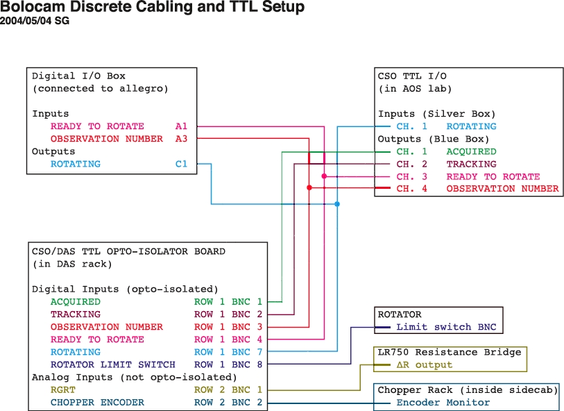
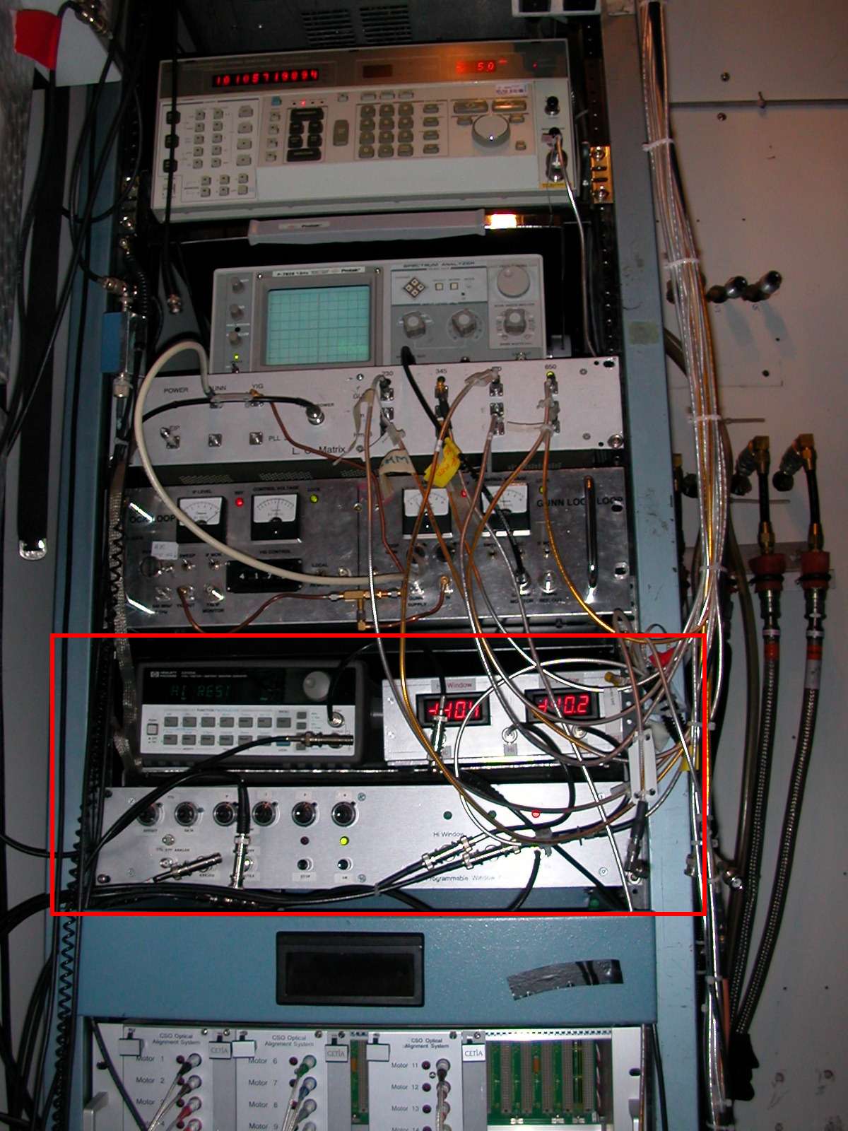
- GRT: Connect the ∆R analog
output on the back of the bridge to the leftmost BNC in row 2 of
the CSO-DAS OPTOISOLATOR BOARD.
(The BNC is labeled as such).
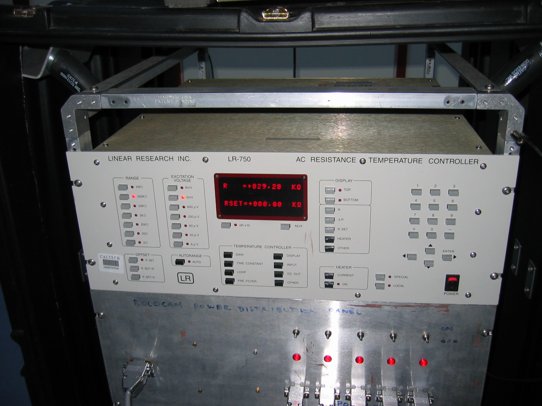
Bridge settings:
Resistance range: 200 kΩThe analog voltage you should see at the DAS on channel 56 is -(RGRT/200kΩ) x 10V
Excitation voltage: 2 mV
RSET = 0 (press the RSET button and enter 0 using the keypad)
∆R x 10 button is off
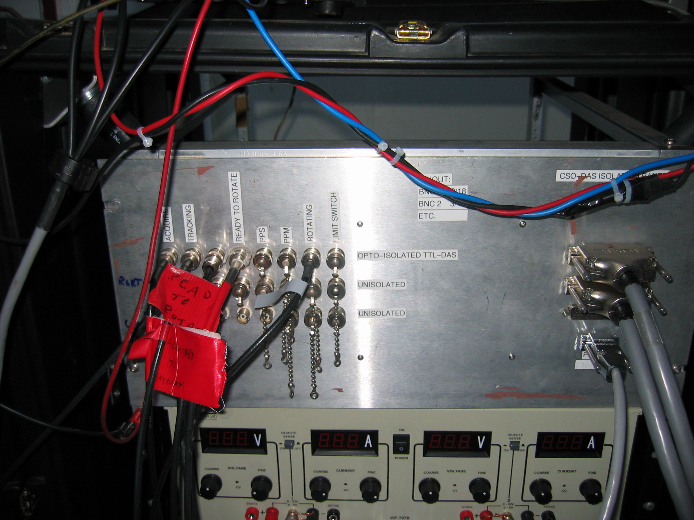
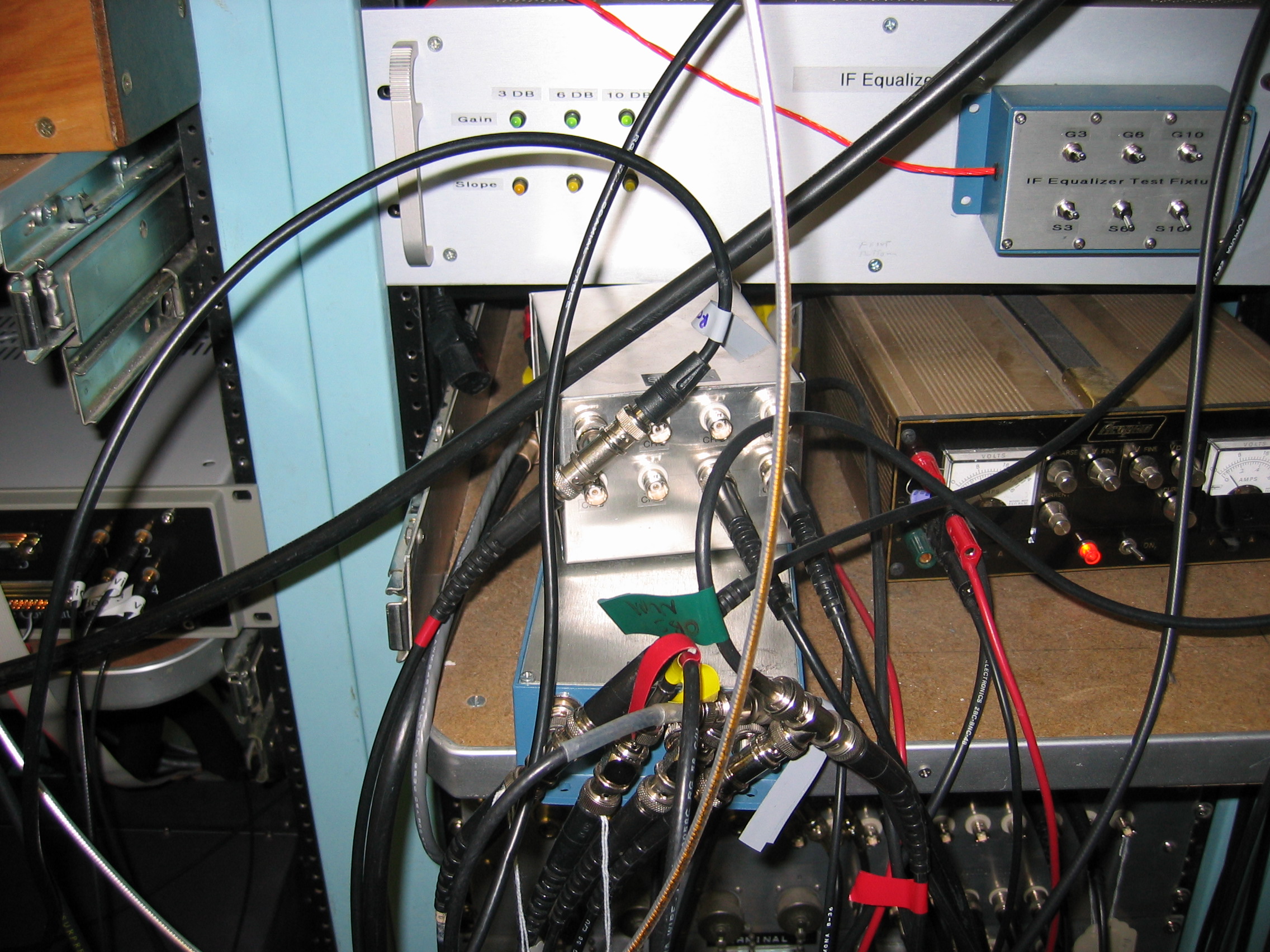
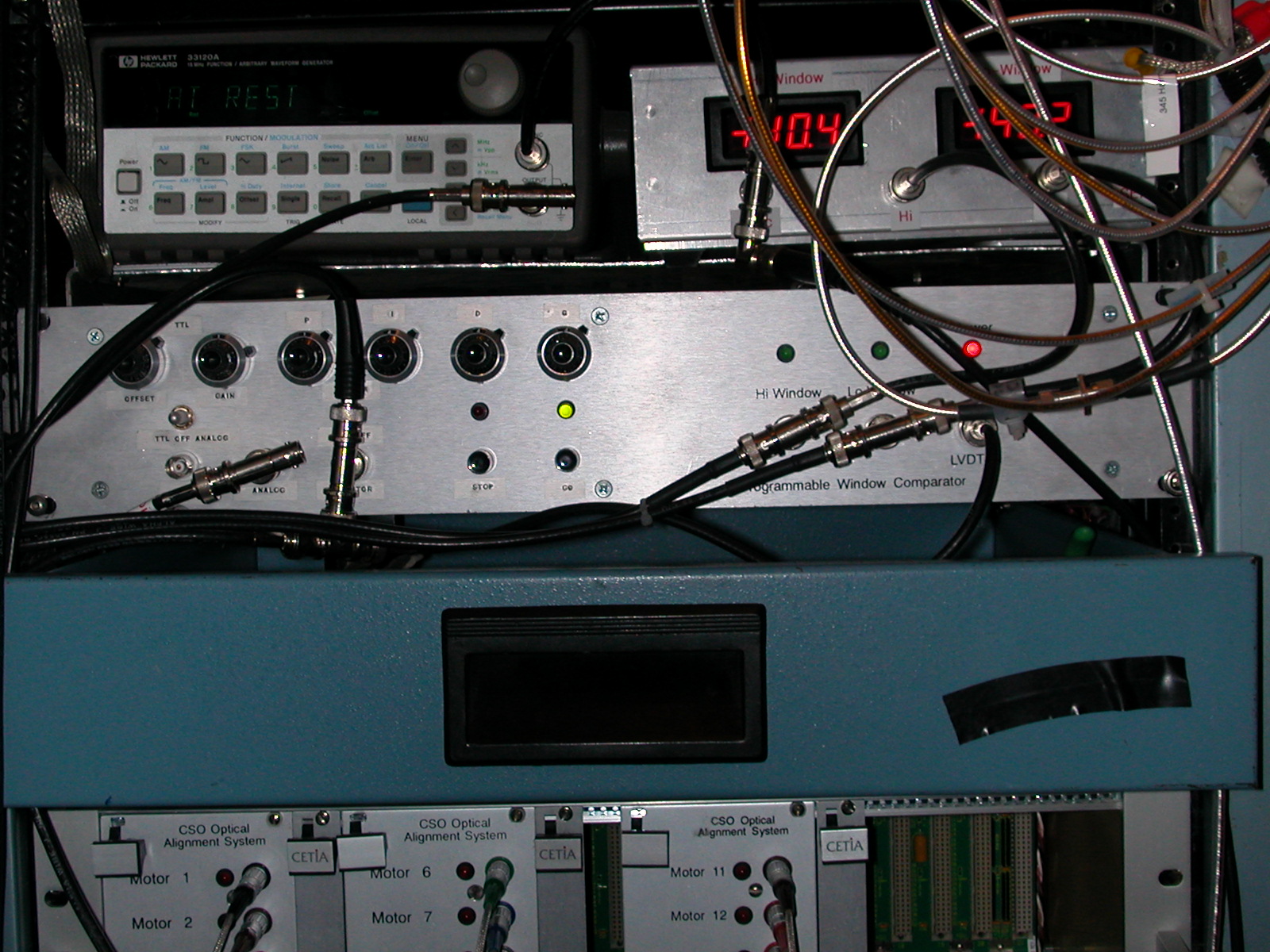
- CHOP_ENC: There should be a cable coming up from the sidecab
that is labeled CHOP_ENC or
some such thing. It carries an analog signal that is proportional
to the chopper position. Connect it to the 2nd BNC from the left
in row 2 of the CSO-DAS
OPTOISOLATOR BOARD. To check, the simplest thing to
do is turn on the secondary chopper using the command
UIP> SECONDARY 90 1
which results in the secondary swinging 90 arcsec (+ beam to - beam) at 1 Hz. The encoder calibration is: voltage offset is 0.388 V, scale is 88.1 arcsec/volt. So, on channel 57 of the DAS, you should see a rolled-off square wave oscillating between -0.123 V and 0.899 V. Turn off the chopper using
UIP> SECONDARY /STOP