Fridge Manual and Monitoring

  1. The Fridge Control Program
    1. How the fridge works
    2. Using the fridge control program
  2. Fridge Cabling Setup
  3. Fridge Power Supply Description
  4. Operating the Power Supplies
    1. Settings
    2. Controlling the supplies manually
    3. Controlling the supplies from the DAS computer
  5. Recovering from Running Out of LHe
  6. Mucking with the AUX Fridge Board
    1. Enabling/Disabling the Array and IC Diodes
    2. Replacing the AUX Board with the Array GRT Jumper Cable
  7. Putting Bolocam to Sleep
    1. Sleep Procedure
    2. Waking up Bolocam
  8. Revision History
Fridge Monitoring Page

Back to BolocamWebPage
Back to ExpertManual


The Fridge Control Program

How the fridge works

The Bolocam refrigerator actually consists of 3 closed-cycle helium refrigerators. 

The UltraCooler (UC) consists of a 3He closed-cycle fridge that cools the focal plane itself.  The InterCooler (IC) consists of both a 4He and 3He close-cycle fridge that cool a buffer stage that lies, thermally, between the 4K LHe bath and the focal plane; the IC thus intercepts most of the heat load from 4K.  The UC is optimized for low temperature at the expense of pumping speed; the IC is optimized for pumping speed at the expense of base temperature.  During quiescent operation, liquid 3He is condensed in both the UC and IC stills and is pumped on by the respective charcoal pumps.  There is no 4He pumping during quiescent operation.

The cycling of the refrigerator is a somewhat complicated procedure.  The trick is that, to condense 3He, it is necessary to provide a condensation point that is below about 2K in temperature.  Thus, a 3He refrigerator cannot be cycled directly when mounted to an ambient pressure (4K) LHe bath.  However, 4He can be condensed at 4K (as is probably obvious), so a 4He closed-cycle refrigerator is used to cool the 3He condensation point(s) to about 1K, then the 3He refrigerators can be started. 

During this procedure, connections between the pumps and the 4K bath must be broken and remade.  For the UC pump, this is done with a passive, weak thermal link.  For the IC pumps, the connection is made by gas-gap heat switches, called the IC 4He and IC 3He heat switches.  A gas-gap heat switch is just a long tube with a reentrant shaft that is connected to a charcoal pump.  When the pump is heated, He gas in the pump is evaporated into the tube and heat can be conducted between the ends of the tube.  When the pump is allowed to cool back to 4K, the pump adsorbs all the gas and the conduction is decreased.

The fridge cycle goes as follows:
  1. The IC 4He heat switch (HS) heater is turned off.  This thermally disconnects the IC 4He pump from the 4K bath so it can be heated.

  2. The IC 4He pump heater is turned on.  This causes the 4He adsorbed in the charcoal pump to evaporate.  The 4He is cooled to 4K by the 4K condensation point (a point along the IC 4He pump tube that is well connected to the 4K bath), condenses, and drips into the 4He still.

  3. Once a sufficient amount of 4He has been condensed, the IC 4He pump heater is turned off and the IC 4He HS heater is turned on.  This causes the pump to cool so that it begins to adsorb 4He from the still; i.e., it begins to pump on the 4He in the IC 4He still.  The UC 3He condensation point is a connection between the IC 4He still and the UC 3He pump tube, about midway up the tube, while the IC3He still is in the same block of copper as the IC 4He still.  Thus, pumping on the IC 4He still cools these points to about 1K.

  4. The IC 3He pump heater is turned on and its gas-gap heat switch is turned off, causing the pump to heat up and the 3He in the 3He pump charcoal to desorb.  This gas is cooled in the IC 3He still where it is in thermal contact with the IC 4He still.  The IC 4He and IC 3He stills are actually made from the same piece of copper; the liquids do not mix, but the two stills are in direct thermal contact.  Thus, the IC 3He gas is cooled to below its condensation temperature in the IC 3He still itself.  This direct contact allows condensation of much more 3He than is condensed during the UC cycle later; the larger 3He liquid volume is needed due to the much larger heat load on the IC.

  5. Midway through the IC 3He cycle, the UC pump heater is turned on, causing the UC pump to heat up and 3He in the UC pump charcoal to desorb.  The UC 3He is cooled by the UC 3He condensation point that is in contact with the IC 4He still, causing the UC 3He to condense and drip into the UC still.

  6. Once a sufficient amount of 3He has been condensed, in both stills, both pump heaters are turned off.  The IC3He gas-gap heat switch is turned on to cool the IC 3He pump.  The UC pump passive heat link pulls the UC pump back down to 4K.  The cooling of the two pumps allows them to begin pumping on their respective stills.  The IC4He pump heat switch is turned off at this point, too.

  7. Once the IC 3He cycle is finished and the IC 3He still cools to its base temperature of about 350-400 mK, the heat load on the UC is reduced tremendously and it cools to its base temperature of about 265 mK

  8. Once the IC 3He cycle is done, the quiescent state is:

One must exercise careful control over how much 4He is condensed during the IC4He cycle.  The goal is to have condensed enough 4He so that the 4He runs out just as one has condensed all of the 3He in the IC 3He and UC stills.  If too much 4He is condensed, then it will remain when the 3He pumping begins.  The 4He has a large heat capacity and will prevent the IC 3He still from cooling to its nominal base temperature.  If too little 4He is condensed, then not enough 3He will be condensed and the UC and IC 3He hold times will be too short.

Here is a picture of a successful fridge cycle; note the cycling of the pump and heat switch temperatures.  There is a 3.5 hour delay period at the start, as indicted by the Time Delay control.  Click on the picture to get a larger copy.  Note the logarithmic vertical scales.  The IC GRT has a voltage offset that makes it untrustworthy above about 700 mK; it isn't really sitting at 800 mK for that extended amount of time, it was warm.


Using the fridge control program

The fridge control program provides both generic temperature monitoring as well as runs a program to cycle the refrigerator.  The program consists of setting various heater voltages and currents via the fridge heater power supplies in the sequence indicated above for specific amounts of time.  The temperature monitoring runs independently of the fridge control.

Loading and starting the program

Using the startup fridge program startFRIDGE

Note that at each steps, the user can just cancel its action by clicking the 'cancel' button.

Using the old-looking but highly reliable vi (been used for years)

The latest version is fridge_cyle_20040513.vi and can be found in C:\documents and Settings\Bolocam\My Documents\Labview vi\FRIDGE .  Before starting the program running, you must:
After setting the above, hit the arrow in the upper left corner of the screen to start the program.  The temperature displays should immediately show some nonzero reading.  The data collection rate is set by a control at the top of the screen.

Starting and viewing the web server

An image of the screen is accessible via the web at http://andante.submm.caltech.edu:8080/Fridge_cycle.html.  This link is available on the main Bolocam web page also.  The screen shot only shows the visible part of the front panel, so make sure you leave the front panel viewing the thermometry displays!  If the web page is not working, or you want to to turn it on, do the following:

Explanation of thermometry

Some explanation of the thermometry is in order:

Getting more control of the cycle (for experts only!)

If you scroll right, you can see some of the machinery and how to get more control of the cycle (double-click to get a bigger version):


Some additional items that are probably only of interest to experts are:

Fridge Cabling Setup

Here is a schematic of the fridge cabling (click on the picture to get a larger version):


See the picture of the rack containing the heater supplies and white breakout box.

Fridge Power Supply Description

The heaters on the fridge are powered from the fridge power supplies, the two Tektronix supplies with blue-green cases sitting in the fridge rack.  Each supply has three outputs.  The first two (the leftmost two) are low current/high voltage (36V/1.5A).  The third one is high current/low voltage (6V/3A).  The first two outputs of the two supplies are used to run the UC pump heater, the IC3He pump heater, the IC4He pump heater, and the JFET heater; all of these heaters have resistances of hundreds of ohms and thus require relatively high voltages at typical currents of 50-100 mA.  The other outputs are used to run the heat switch heaters, which are 10 kΩ heaters and only need 5-6 V and less than 1 mA.

Identifying the parts of the supplies (see the closeup):
The outputs of these power supplies go to BNC connectors on the front of the white breakout box (a 19"-rack-width box) in the fridge rack.  This box converts to the DB50 cables that go off to the dewar.


Operating the Power Supplies

Settings

Currents vs. voltages:

Nominal settings: These are the "nominal" settings for the supplies, when you don't want any of the heaters on.  Do this with the outputs OFF so that you can see the limits, not the actual values.  Once you have made the settings, you should hit the OUTPUT button to turn the outputs ON.  It's actually not too important to set these nominal values anymore; as of April, 2004, the fridge control program initializes all the supplies (except the JFET supply) as necessary at the start of the cycle.

Controlling the supplies manually

If you want to control the PSUs manually, here is the information you need.  See the picture to identify the buttons.

Enabling front panel control: The LOCAL button makes it possible to control the supply using the front panel; if the supply is not in LOCAL mode, the front panel is locked out and the supply is controlled by GPIB.  You can feel free to press the LOCAL button at any time, even during a fridge cycle -- the fridge computer can still control the supplies.  If the power supplies do not appear to be responding even after pressing the LOCAL button, it may be because the fridge_cycle program is simultaneously trying to read them.  Set the sample rate on fridge_cycle to some relatively large value (less than 1 per minute) and then attempt to program the supplies.  Set the sample rate for fridge_cycle back to its original value afterward.

Enabling the outputs: There is an OUTPUT button that enables/disables the outputs.  The OUTPUT button controls relays that actually connect the internal supplies to the output banana jacks.  Thus, even if you have set the output currents and voltages, they won't actually be activated until the OUTPUT button has been pressed.  Conversely, if the output currents and or voltages are set to 0, then pressing the OUTPUT button will not do anything except energize the relay; current will not necessarily flow.  On the display, in the upper right corner, there is an OUT light that will be on if the outputs are enabled (1st row, 4th column in matrix of status lights).

How to select which channel is displayed:  To set which output is displayed/controlled via the keypad: find the keys that say OUT1, OUT2, OUT3 in light blue above them.  Press the SHIFT button and then press whichever of these buttons corresponds to the output you want to display/control.  Note that the supply must be in LOCAL mode for these (or any other) buttons to work.  The first column of the matrix of status lights has three lights indicating which supply is being displayed.

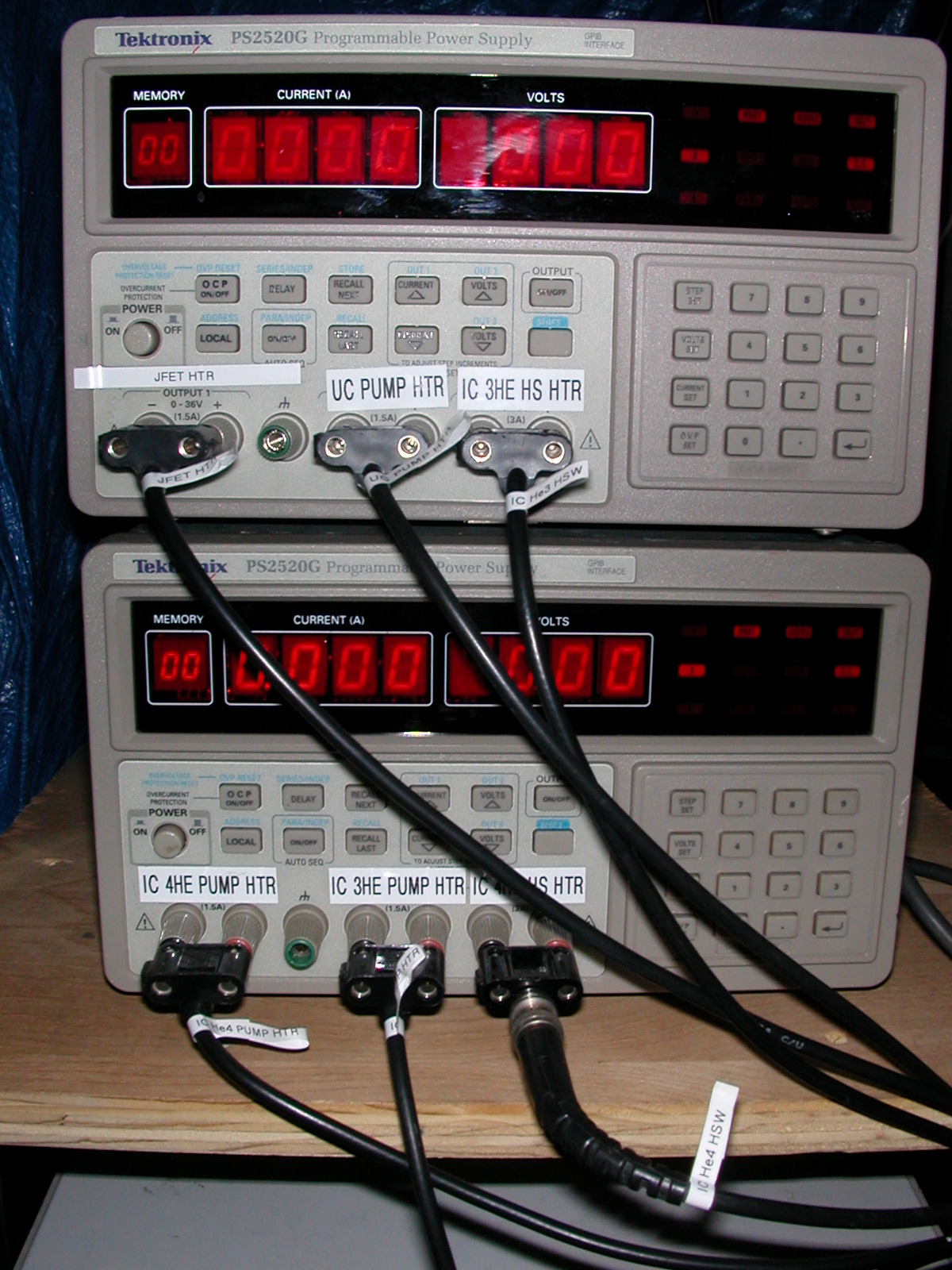
How the displays work: The displays do different things depending on what state the supply is in.  When the outputs are off (OUT light off), then the displayed current and voltage are the values that have been set (see To set outputs currents and voltages below).  When the outputs are on (OUT light on), then what is shown is the actual current and voltage.  What these are depends on the settings.  Though you set a current and a voltage, the supply can't necessarily satisfy both of these settings.  It picks the "lower" one.  For example, if you set 50 mA and 35 V for the UC pump heater, which has a total resistance (including leads) of maybe 250 ohms, then you will see 0.050 A and 12.5 V on the display because 50 mA x 250 ohms = 12.5 V < 35 V.  The current and voltage settings thus act in some sense as limits for each other.

To set output currents and voltages:
  1. Select the output you want.

  2. On the numeric keypad are CURRENT SET and VOLTS SET buttons.  Press the one you want.

  3. Enter the value you want to set using the buttons, e.g., for 35 mA, hit 0 . 0 3 5 followed by the enter button, which is an arrow with a right angle in it.

  4. What you see on the display will depend on whether the outputs or on or off -- see How the displays work above.

Controlling the supplies from the DAS computer

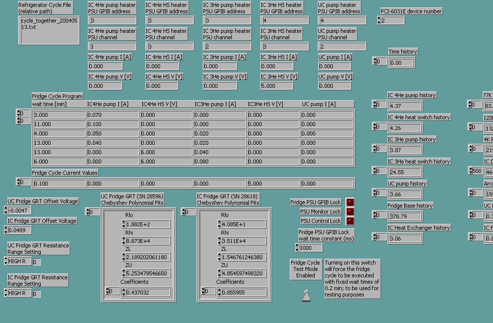
There is now a program for direct control of the power supplies available on the DAS computer.  Go to the desktop of the DAS computer, open the shortcut to the FRIDGE folder, and double-click on ManualPSUControl.   Hit the arrow in the upper left corner to start the program.  The bottom two rows of displays indicate the current power supply settings.  Set the middle two rows of controls to the desired settings.  Note that you must set all the controls appropriately, even the ones you don't want to change; when the program commands the power supplies, it sets all of the control values.  When you are ready to issue the command, press the button on the left side of the panel that says "Press to set PSU values".  The bottom two rows of displays should then update to reflect your new settings.  If you have problems, press the Reset button in the upper left and try setting the power supply values again.

Note that the current and voltage indicators show the actual currents and voltages, not the programmed ones.

There may be interference of this program with the standard fridge cycle program if they try to communicate simultaneously with the fridge power supplies.  To avoid such interference, set the fridge control program to a slow sampling rate (1 per minute or slower) before starting ManualPSUControl, and then do your manual commands in the interval between samplings by fridge_cycle, and then stop ManualPSUControl.  If the programs seem to interfere (very slow reading of supply settings, nonsense or mixed-up values), then just kill ManualPSUControl using the red stop-sign button in the upper left of the screen and try again.  Note that the normal stop button on the front panel of ManualPSUControl will not work if it is hung in the communication cycle.


Recovering from Running Out of LHe

When you run out of LHe, everything warms up.  If the array gets too warm, the fridge cycle will fail because the array will not cool enough to condense 3He in the UC still.  So you have to cool the array down by hand prior to starting the fridge cycle.  To do this, do the following:
You do not need to worry about the IC getting too warm.   There is a passive heat switch connecting the IC to the 4K bath, so the IC cools off automatically once the LHe bath has been refilled.  The IC cools off much more quickly than the UC does, so getting the UC cold assures that the IC has also gotten cold.


Mucking with the AUX Fridge Board

The AUX fridge board reads out a number of diode thermometers and provides access to the array GRT and heater.  During cooldown to 4K, the array and IC diodes are read out using this board.  Before cycling the fridge, however, it is necessary to disable these diodes because they dissipate too much power.  Alternately, when Bolocam is set up for regular observing, the AUX board is completely removed and a jumper cable used to allow access to the array GRT only.  Here are instructions for making these changes.

Enabling/Disabling the Array and IC Diodes

It is straightword to disconnect and reconnect the array and IC diode readouts.  These readouts are located on the AUX fridge board, which is the rightmost board when viewing the boards (as in this picture, though note that the AUX board is not in place in this picture -- it would go in the slot in which you see the black-and-white jumper cable).
  1. Open the top of the E-box (if it is closed) and turn off the power switch to the AUX board (all the way at one end of the set of power switches -- the switches are in the same order as the boards).

  2. Open the E-box and remove the board in the rightmost slot.  You will likely have to disconnect a cable going from the face of the board to a feedthrough connector on the bottom of the E-box.

  3. The board will look like this (click on the picture for a larger version):


    Notice the handwritten labels and the yellow jumpers.  Readout of a given diode is enabled or disabled by the appropriate yellow jumpers.

  4. Disconnect or reconnect the array and IC diode jumpers to match one of these pictures (click for a larger version):
    NEED BETTER FOCUSSED PICTURES!

    Connected
    Disconnected


    There are two possible configurations for the jumpers:


    The two different configurations drive current through the diode in opposite directions.  When reconnecting the diodes, you may have to experiment with both configurations to find the right one.  A handy way to remember which one is correct is to, when you disconnect the jumper, only disconnect the right side connections, as demonstrated in the "Disconnected" picture above; then, when someone comes to reconnect, he only needs to reconnect the right side, for which there is only once choice of how to do it.

  5. Replace the board in its slot and turn its power switch back on.  (If you are reinserting the board for the first time after observing, remove the black-and-white jumper cable that is occupying the slot.  You will likely also see a black-and-white GRT cable connected to the outside port of the feedthrough connector on the bottom of the E-box that corresponds to this slot.  Disconnect that cable too.)

  6. Connect a long DB50F-DB50M cable from the top connector on the face of the board to the corresponding feedthrough connector on the bottom of the E-box.

  7. If it is not already connected, connect the AUX fridge monitor DB50 thermometry cable to the same feedthrough port.  This cable will originate from the back side of the white thermometry breakout box.

  8. Check that you are now seeing reasonable temperature readings from the 4K Diode, Array Diode, and IC Diode on the fridge monitoring screen.  If any of the diode readings are nonsense, the polarity jumpers may need to be modified.

Replacing the AUX Board with the Array GRT Jumper Cable

See the link to the Electronics page.


Putting Bolocam to Sleep

There are occasions where Bolocam will be on hiatus for a number of nights, but then will come back into service.  During such periods, it is sensible to put Bolocam to "sleep" to minimize cryogen usage.

Sleep Procedure

Putting Bolocam to sleep is easy:
  1. Restart the AUX fridge readout electronics as instructed above, with the Array and IC diodes enabled.  Make sure you have reasonable thermometry readings for the 4K Diode, Array Diode, IC Diode, and all the pumps and heat switches.

  2. Turn off power to all the boards in the E-box except the two end boards, which are the thermometry boards.  This turns off power to the JFETs.

  3. Allow the LHe to run out.

  4. Monitor all the diode thermometers during the sleep period.  The 77K and 120K diodes should cool because the JFETs are off.  The remaining diodes will all slowly warm after the LHe has run out.

  5. If the LHe layer diodes (4K, Array, IC, pumps and heat switches) approach 80K, you need to keep them from warming further as follows:

    Maintain until you need to wake up Bolocam.

Waking up Bolocam

You need to plan ahead here to ensure Bolocam is fully recooled in time for your observing, as well as to ensure the JFETs have had time to reheat to their nominal temperature.  The array takes the longest time to cool, so the time needed is set by how warm the array is.  Typically, one will have let the array warm to about 80K and then hold it there by LN or LHe in the LHe bath.  From 80K, it takes about 15 hrs to recool the array to 4K.  The procedure for recooling is the same as for the normal LHe cooldown, see those instructions elsewhere.  Don't forget to also use the JFET heater to quickly heat the JFETs.

A reasonable schedule for the recool is to start the recool procedure 1 day before the day that Bolocam is needed again; e.g., if Bolocam's first night back on is a Wednesday, start the recool on Tuesday.  The recool can be started at the end of the day.  Though note that the first LHe fill may run out quickly, so one should fill with LHe 1-2 hrs before the end of the day and then top of just prior to leaving.

You will still need to cycle the fridge after recooling the array to 4K, so make sure you leave time for that too.

You will have already turned the JFETs on during the JFET heating.  You may turn on the remainder of the electronics boards whenever you like.  Prior to observing, you will have to remove the AUX board, reinstall the array GRT jumper cable, and connect the array GRT to the resistance bridge; how to do this is explained elsewhere.


Revision History


Questions or comments? Contact the Bolocam support person.